Method for reducing surface roughness in a welded seam of an imaging belt

Inactive Publication Date: 2003-09-16
XEROX CORP
View PDF7 Cites 10 Cited by
  • Summary
  • Abstract
  • Description
  • Claims
  • Application Information

AI Technical Summary

Benefits of technology

In one aspect of the invention, there is provided a method for reducing surface roughness in a welded seam of an imaging belt, the imaging belt comprising first and second ends, the first and second ends overlapping and thereat joined by a welded seam, the welded seam comprising a surface roughness, the belt comprising an imaging layer, a glass transition temperature corresponding to the imaging layer, the process comprising the steps of: at a fixed pressure, compressing a belt portion comprising the welded seam and belt end portions adjacent thereto and, while compressing: heating the welded seam to a heating temperature near but less than the glass transition temperature; then cooling the welded seam to a cooling temperature; the compressing, heating and cooling reducing the surface roughness; and then determining when the surface roughness is satisfactory.

Problems solved by technology

When ultrasonically welded into a belt, the seam of flexible multilayered electrophotographic imaging member belts may occasionally contain undesirable high protrusions such as peaks, ridges, spikes, and mounds.
These seam protrusion spots present problems during image cycling of the belt in the machine because they interact with cleaning blades to cause blade wear and tear which ultimately affect cleaning blade efficiency and service life.
Moreover, the protrusion high spots in the seam may also interfere with the operation of subsystems of copiers, printers and duplicators by damaging electrode wires used in development subsystems that position the wires parallel to and closely spaced from the outer imaging surface of belt photoreceptors.
Both the time consuming procedure of manual inspection and the number of seamed belts rejected due to the presence of high seam protrusions constitute a substantial financial burden on the production cost of imaging member belts.
While the above references disclose a variety of approaches for improving the seam of flexible imaging member belts, these disclosed approaches are either insufficient to meet the expectation, or often time introduce new set of undesirable outcomes such as seam vicinity imaging member wrinkling and belt circumferential dimension shrinkage.

Method used


Image

  • Method for reducing surface roughness in a welded seam of an imaging belt
  • Method for reducing surface roughness in a welded seam of an imaging belt
  • Method for reducing surface roughness in a welded seam of an imaging belt

Examples


Embodiment Construction

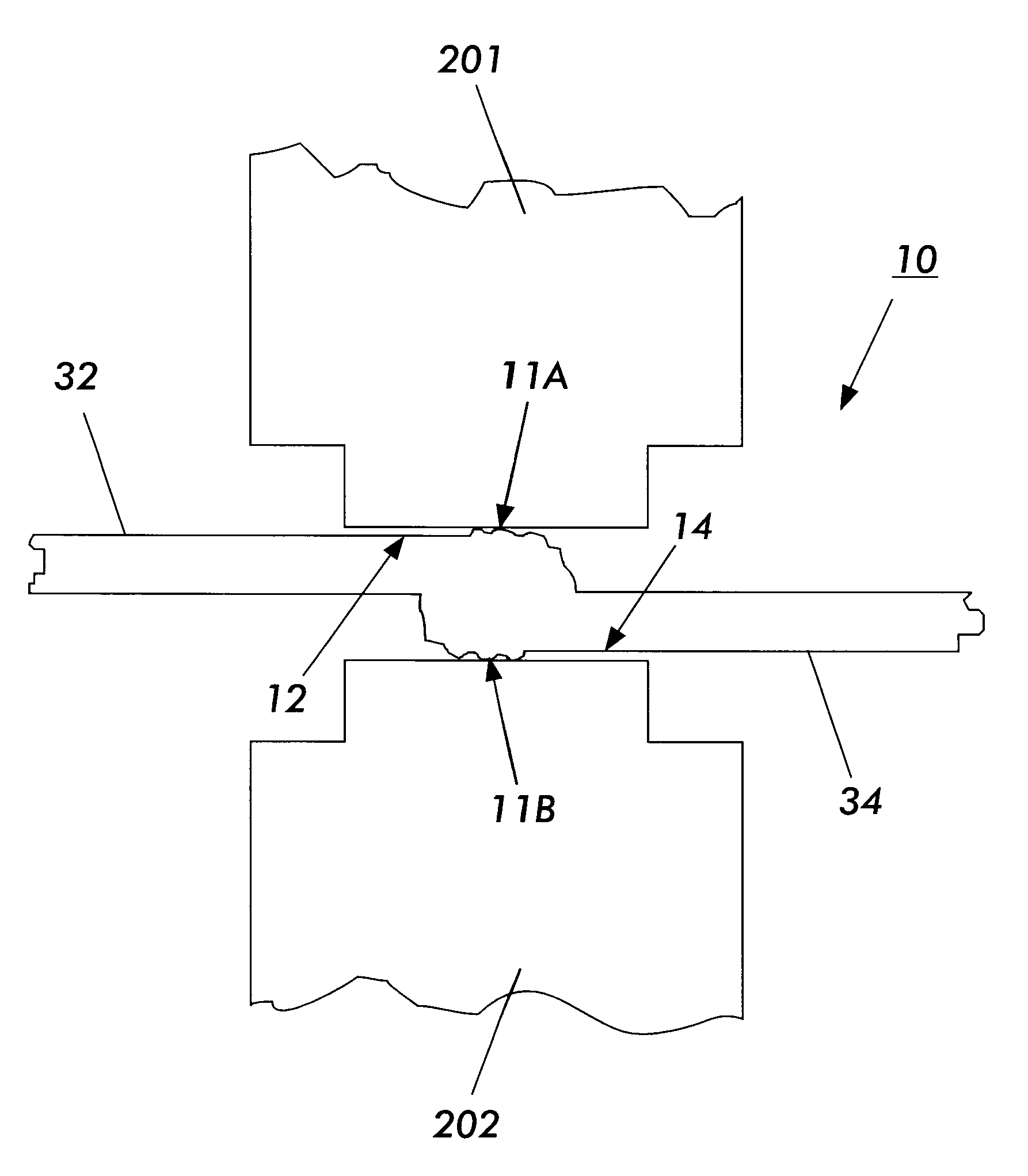
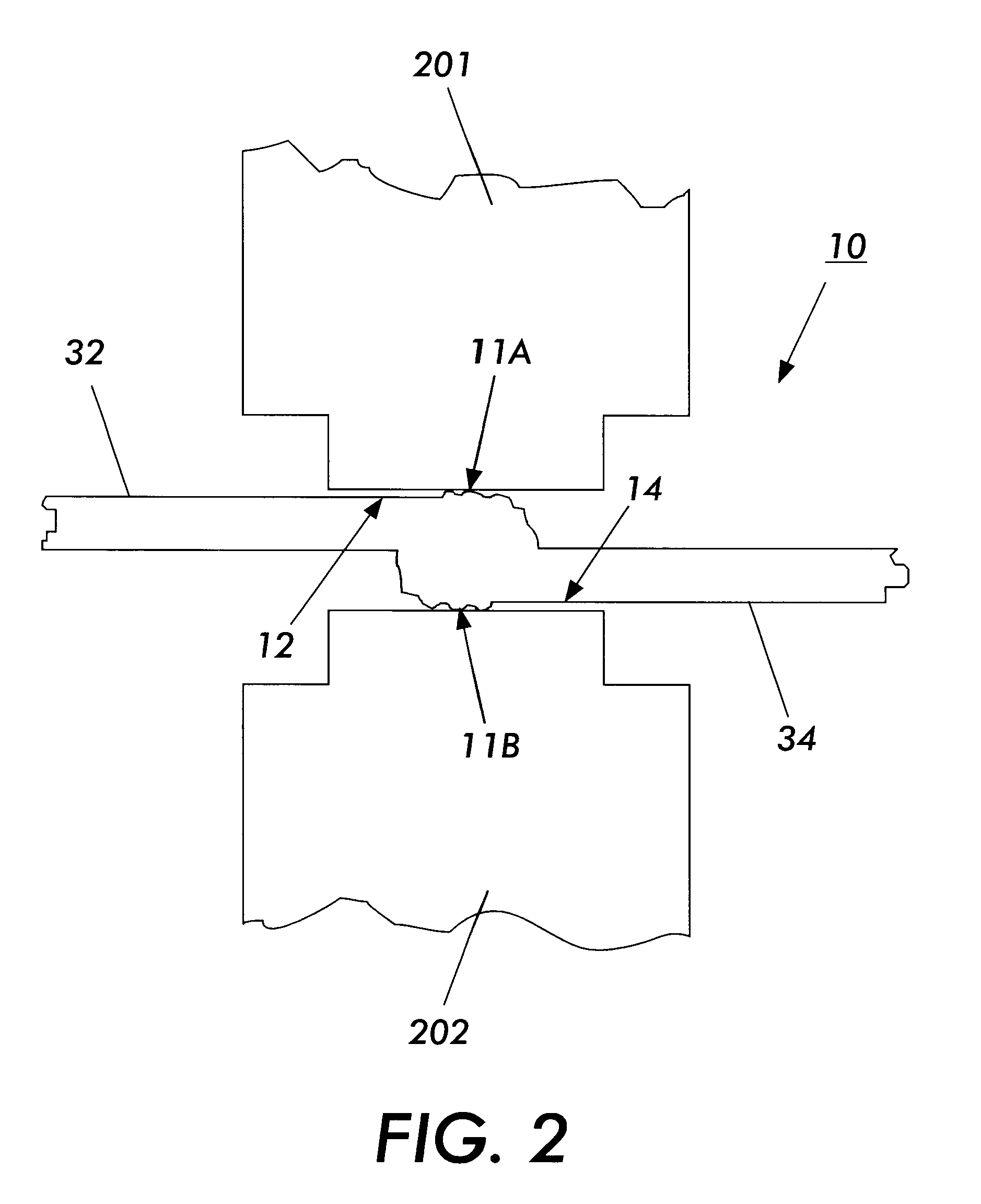
In brief, a process for reducing surface roughness in a welded seam of an imaging belt is provided. In accordance with the present invention, the welded seam is treated by compressing a portion of the belt comprising the welded seam and adjacent belt portions and, while compressing, heating the welded seam to a heating temperature near but less than the glass transition temperature of the imaging layer of the belt, then cooling the welded seam to a cooling temperature. The compressing continues while the heating and cooling steps are repeated until the surface roughness is determined to be satisfactory. The process then ceases.

As used herein, the words "process" and "method" have identical meanings and may be used interchangeably.

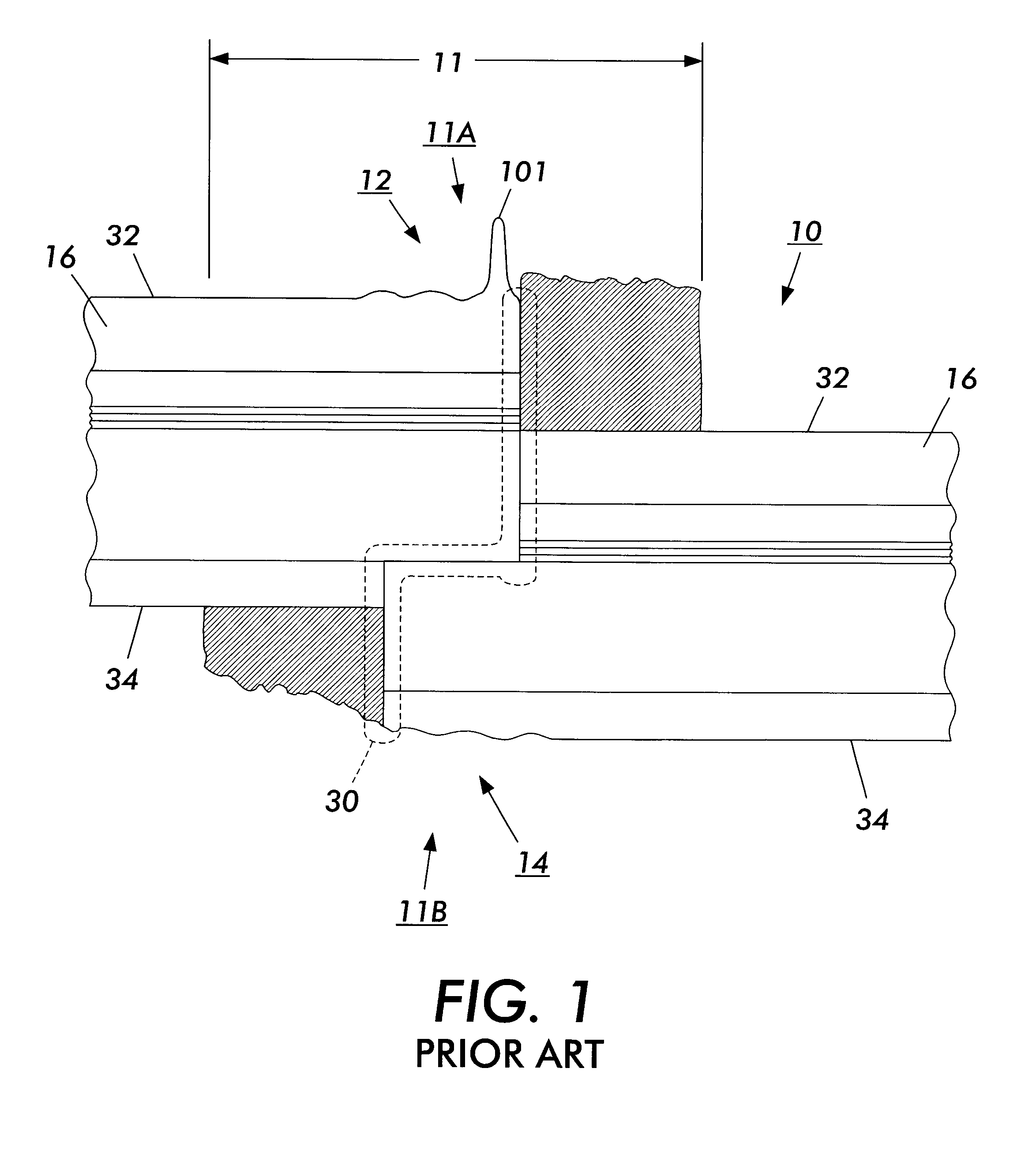
Referring now to FIG. 1, there is shown a prior art electrophotographic imaging belt 10 with a first end 12 and a second end 14. The imaging belt 10 is flexible, and includes an outer surface 32 and an inner surface 34. As shown, the first end 12 and the se...


PUM

PropertyMeasurementUnit
Temperatureaaaaaaaaaa
Fractionaaaaaaaaaa

Abstract

A welded seam of an imaging belt comprises a surface roughness. To reduce the surface roughness, the welded seam is treated by compressing a portion of the belt comprising the welded seam and adjacent belt portions and, while compressing, heating the welded seam to a heating temperature near but less than the glass transition temperature of the imaging layer of the belt, then cooling the welded seam to a cooling temperature. The compressing continues while the heating and cooling steps are repeated until the surface roughness is determined to be satisfactory. The process then ceases.

Description

FIELD OF THE INVENTIONThis invention relates in general to imaging belts and, more specifically, to a process for reducing surface roughness in a welded seam of an imaging belt.BACKGROUND OF THE INVENTIONFlexible imaging member belts in electrostatographic imaging system are well known in the art. Typical flexible imaging member belt include, for example, electrophotographic imaging member belts for photoreceptors for electrophotographic imaging systems, ionographic imaging member belts or electroreceptors for electrographic imaging systems, and intermediate image transfer belts for transferring toner images used in an electrophotographic or an electrographic imaging system. These belts are usually formed by cutting a rectangular sheet from a web containing at least one layer of thermoplastic polymeric material, overlapping opposite ends of the sheet, and joining the overlapped ends together to form a welded seam. The seam extends from one edge of the belt to the opposite edge. Gene...

Claims


Application Information

Patent Timeline
IPC IPC(8): B29C65/00G03G5/043G03G5/147G03G5/10G03G7/00F16G3/10G03G5/00G03G15/00G03G15/16G03G21/00
CPCB29C65/08B29C65/7847B29C66/03241B29C66/1122B29C66/4322B29C66/4324B29C66/49B29C66/723B29C66/73117B29C66/91411B29C66/91445B29C66/91945B29L2031/709B29L2031/764G03G5/043G03G5/10G03G5/147G03G7/00G03G15/162G03G15/754
Inventor YU, ROBERT C. U.HAMMOND, WILLIAM A.SCHLUETER, JR., EDWARD L.THORNTON, CONSTANCE J.
Owner XEROX CORP
Why Eureka
Try Eureka