Delay stage circuitry for a ring oscillator

a delay stage and oscillator technology, applied in the field of clock synchronization circuitry, can solve the problems of difficult to minimize, limited number of phase signals that can be generated, and offset and deadband problems

Inactive Publication Date: 2004-03-30
RAMBUS INC
View PDF52 Cites 54 Cited by
  • Summary
  • Abstract
  • Description
  • Claims
  • Application Information

AI Technical Summary

Problems solved by technology

Some prior phase locked loop implementations using ring oscillators suffer phase offset and deadband problems, which are difficult to minimize without compromising one or the other.
One disadvantage of prior ring oscillators is that the number of phase signals that can be generated are limited by the number of inversion elements contained in the ring oscillator.
The number of inversion elements is, in turn, limited by the length of time dela

Method used


Image

  • Delay stage circuitry for a ring oscillator
  • Delay stage circuitry for a ring oscillator
  • Delay stage circuitry for a ring oscillator

Examples


Embodiment Construction

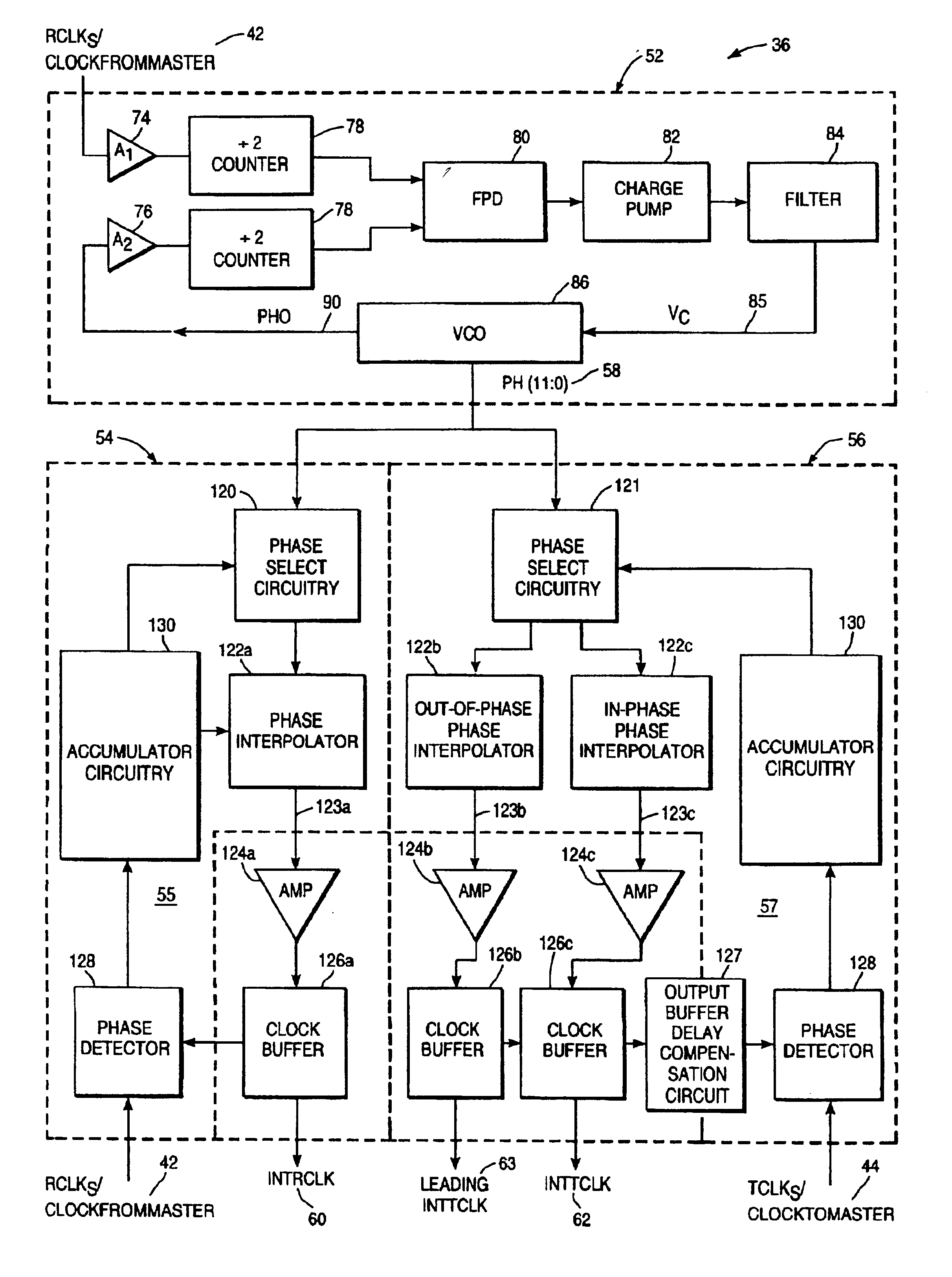
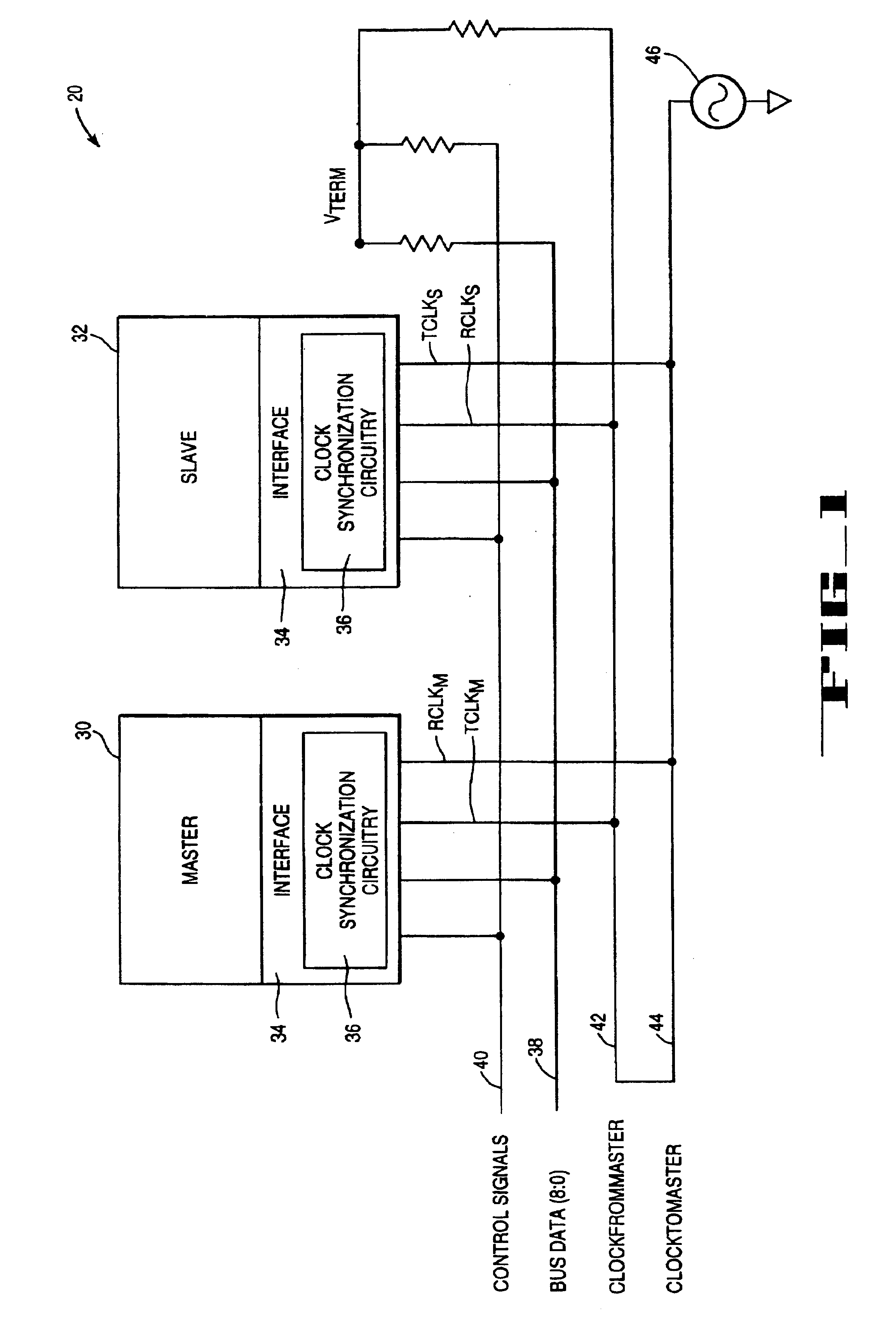
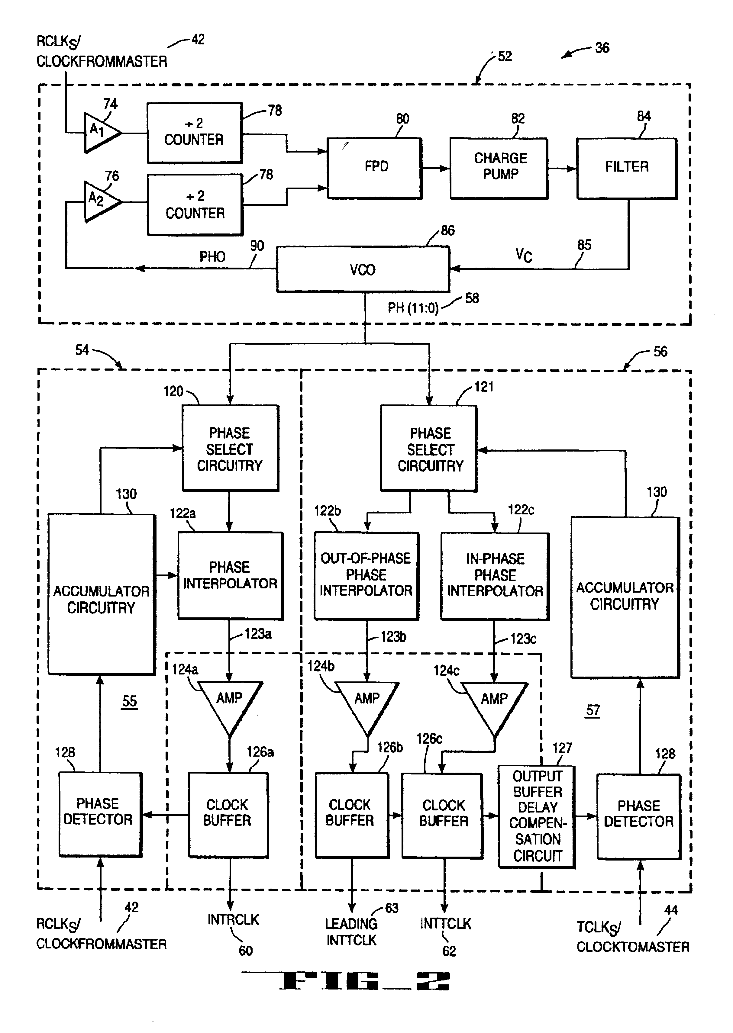
FIG. 1 is a block diagram of a high speed digital computer bus system 20. Devices 30 and 32 use clock synchronization circuitry 36 to synchronize the transfer of data between data bus 38. Clock synchronization circuitry 36 is a cascaded phase locked loop (PLL) 36. The main loop of PLL 36 utilizes a ring voltage controlled oscillator (VCO), which includes an even number of cascaded delay stages of the present invention. Two subloops coupled to the main loop perform fine phase tuning according to the method and circuitry of the present invention to generate two internal clock signals.

As will be described in more detail below, each delay stage of the present invention generates two complementary output signals using a differential amplifier. Coupled between the two complementary output signals, two clamping devices limit the peak-to-peak voltage swing of the complementary output signals. When the delay stages are cascaded together, they provide twelve different phase signals that are u...


PUM


Abstract

A ring oscillator includes an even-numbered plurality of ring coupled delay stages. Each delay stage includes a differential amplifier, a voltage clamping circuit, and a current source. The differential amplifier receives first and second input signals from a preceding delay stage. The differential amplifier provides a first output signal and a complementary second output signal at first and second nodes, respectively. The voltage clamping circuit is coupled between the first and second nodes to limit a peak-to-peak voltage swing of each of the first and second output signals. The current source is coupled to the differential amplifier and varies a bias current in accordance with a delay bias voltage.

Description

FIELD OF INVENTIONThe present invention relates to clock synchronization circuitry including a cascaded phase locked loop. In particular the present invention relates to a delay stage for a ring oscillator and a fine phase tuning circuitry, both used in the cascaded phase locked loop.BACKGROUND OF THE INVENTIONClock synchronization in integrated circuits is typically performed by a phase locked loop (PLL).Some prior PLLs use a ring oscillator as a voltage controlled oscillator. A ring oscillator is a chain of inversion elements coupled together in a negative feedback fashion, with each element contributing a delay amount which adds up to half an oscillation period. Some prior phase locked loop implementations using ring oscillators suffer phase offset and deadband problems, which are difficult to minimize without compromising one or the other.One disadvantage of prior ring oscillators is that the number of phase signals that can be generated are limited by the number of inversion el...

Claims


Application Information

Patent Timeline
IPC IPC(8): H03K3/0231H03K3/354H03L7/08H03L7/06H04J3/06H03L7/099H03K3/00H03L7/07H04L7/033
CPCH03K3/0231H03K3/354H03L7/06H03L7/07H03L7/0996
Inventor LEUNG, WINGYUHOROWITZ, MARK A.
Owner RAMBUS INC
Why Eureka
Try Eureka