
Laser cutting method for forming magnetic recording head sliders

a technology of magnetic recording head and slider, which is applied in the manufacture of instruments, manufacturing tools, and recording information storage. it can solve the problems of affecting the manufacturing cost of the sawing process, affecting the sawing process, and causing a variety of physical damage to the slider material

Inactive Publication Date: 2006-03-07
WESTERN DIGITAL TECH INC
View PDF17 Cites 31 Cited by
  • Summary
  • Abstract
  • Description
  • Claims
  • Application Information

AI Technical Summary

Benefits of technology

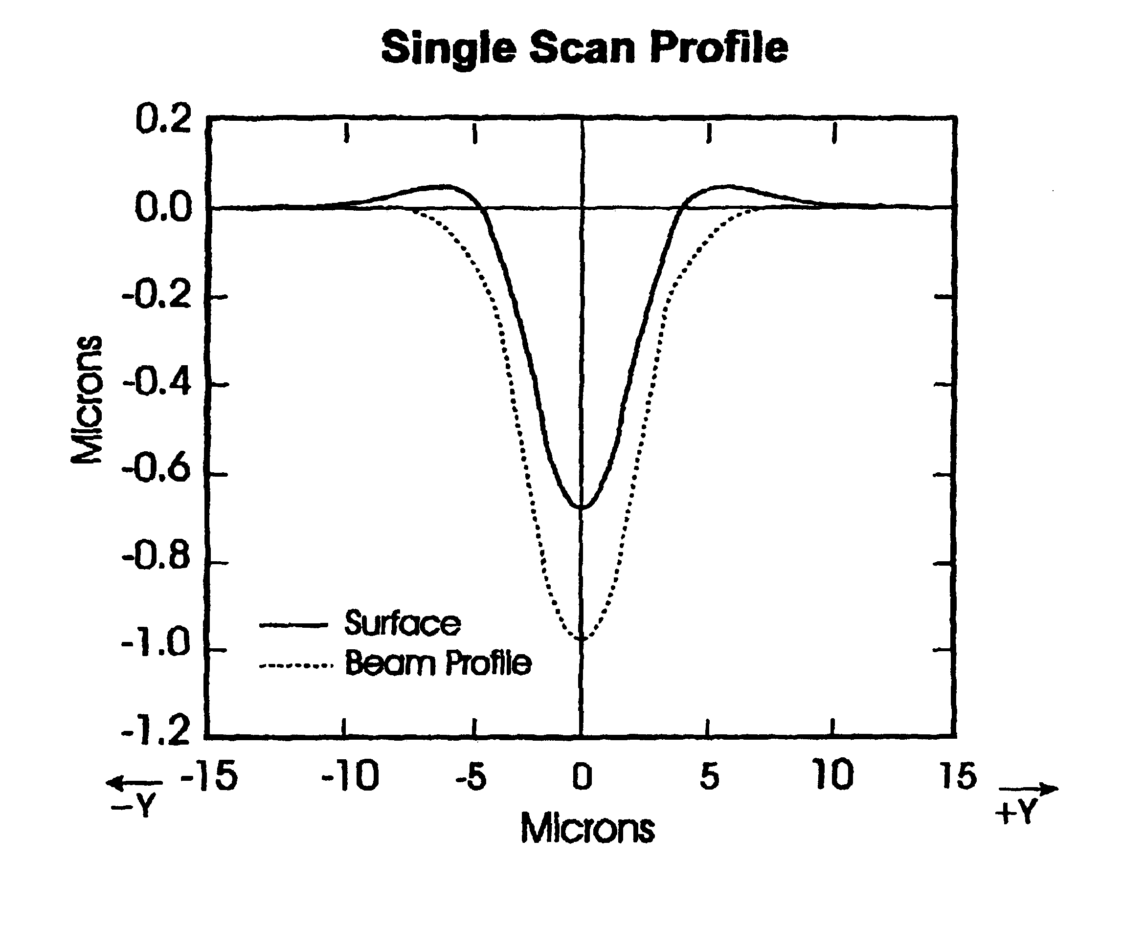
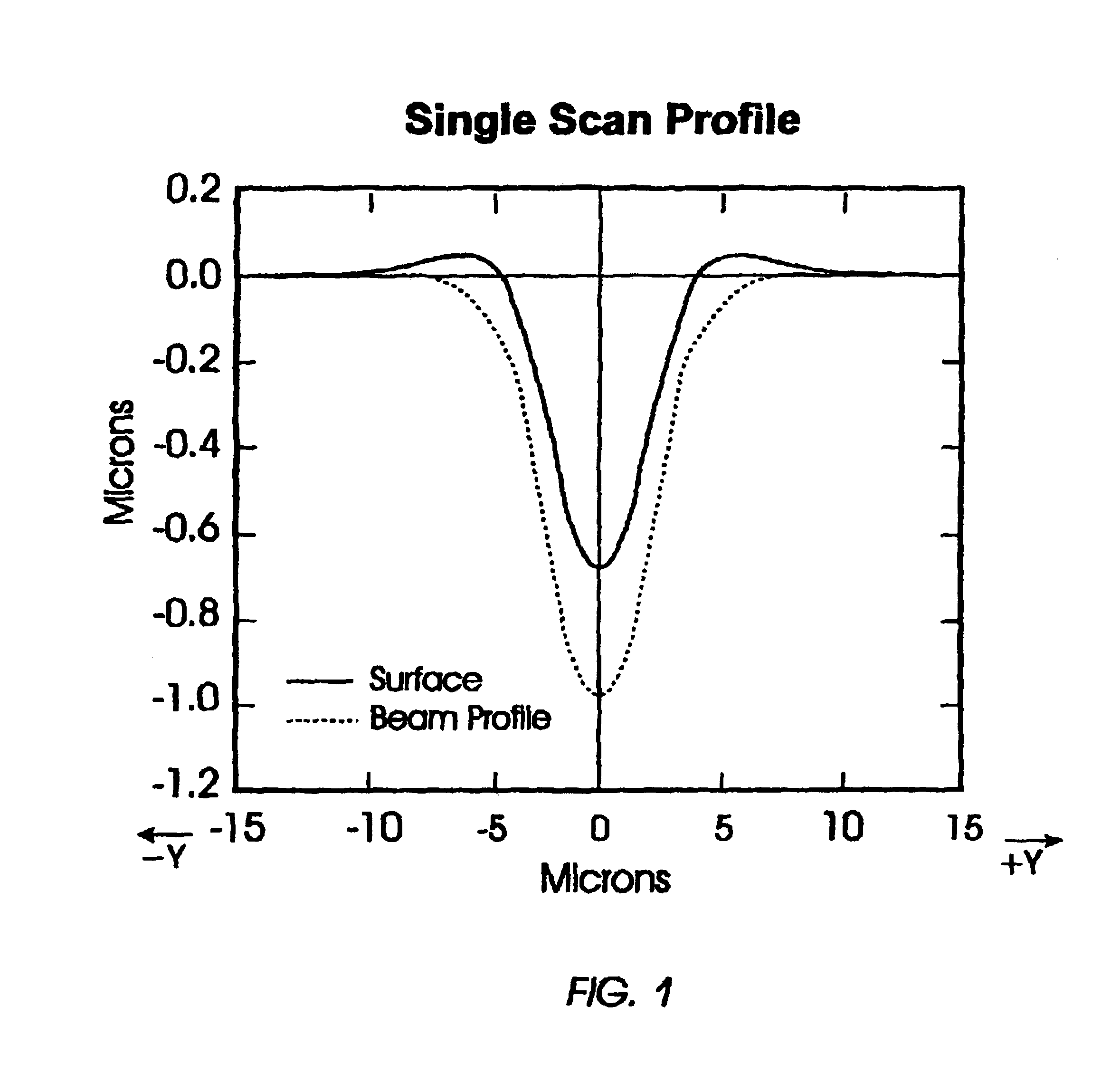
[0007]The method of the present invention simultaneously partially cuts the sliders from the wafer row and blends the edges at the disk sides of the sliders, thereby eliminating a subsequent separate edge blending step. The laser cutting process allows more sliders to be formed from a single ceramic wafer since substantially less ceramic material is removed than would be removed if the conventional diamond-tipped sawing process were used.

Problems solved by technology

There are many disadvantages to the sawing process.
The manufacturing cost of the sawing process is affected by several physical limitations.
The sawing process with its associated large mechanical and frictional forces tearing into the slider material also produces a variety of physical damage, such as chipping, scratching, and cracking of the sliders and delamination of the patterned layers of the read / write heads.
Because the sawing process includes significant rubbing it can also cause the accumulation of static electrical charge, which can damage the read / write heads when discharged.

Method used


Image

  • Laser cutting method for forming magnetic recording head sliders
  • Laser cutting method for forming magnetic recording head sliders
  • Laser cutting method for forming magnetic recording head sliders

Examples


Embodiment Construction

[0014]The ceramic wafers from which the sliders are fabricated according to the method of the present invention are commercially available from various sources, such as 3M Corporation and Sumitomo.

[0015]The machining of sliders by laser ablation to create recesses in the slider disk side and thereby form the rails of the ABS is known, as described in U.S. Pat. No. 4,835,361. The previously cited IBM '048 patent suggests that partial cuts in the wafer row may be formed by laser ablation, but gives no details of such a process.

[0016]The cutting of material by laser ablation has been used for a number of applications that are not sensitive to edge quality or cleanliness, so the mere suggestion that it can be used for scoring sliders in a ceramic wafer row does not teach that a practical process can be developed. It is known that standard laser processing produces an edge quality that is not as desirable as that resulting from diamond saw slicing, particularly in regard to material prot...


PUM

PropertyMeasurementUnit
Diameteraaaaaaaaaa

Abstract

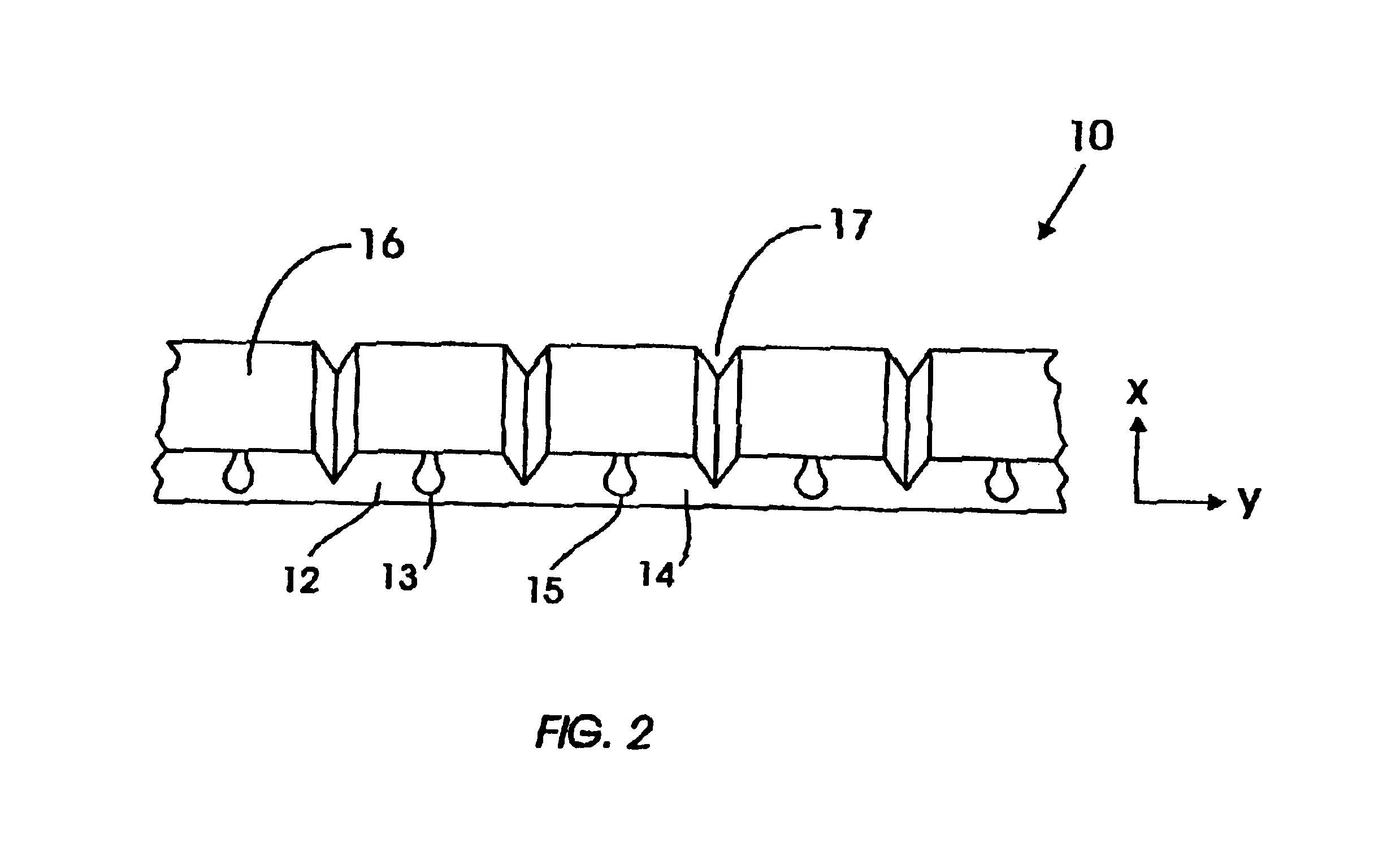
A method for cutting a ceramic wafer to form individual sliders for use in supporting the read / write heads in magnetic recording disk drives uses multiple parallel scans of a pulsed laser to ablate the ceramic material. After the wafer has been cut into individual rows, a pulsed laser beam is directed to that surface of the row that will become the disk sides of the sliders (i.e., the sides of the sliders that will face the disks in the disk drive). The laser is pulsed as the laser spot is moved along a first scan line across the surface of the wafer row to form a generally V-shaped trench. The laser spot is then moved in a direction generally perpendicular to the first scan line a distance less than the laser beam diameter, and then pulsed while the laser spot is scanned along a second line generally parallel to the first scan line. This slight offset of the laser beam during the second scan blends the edges of the wafer surface at the trench to remove protrusions formed at those edges by the first laser scan. The laser is then moved to the other side of the first scan line a distance less than the laser beam diameter and a third scan is made to blend the other edge. One of more subsequent laser scans can be made along the first scan line to either cut deeper or to cut completely through the wafer row to completely separate the sliders.

Description

TECHNICAL FIELD[0001]This invention relates generally to the manufacture of air-bearing sliders used for supporting the read / write heads in magnetic recording hard disk drives, and more particularly to a method for separating sliders from rows of uncut sliders.BACKGROUND OF THE INVENTION[0002]In a hard disk drive each magnetic recording data storage disk surface has an associated slider. The slider has a side that faces the disk that includes an air-bearing surface (ABS), and a back or trailing side that supports the patterned read / write head. In operation of the disk drive, the disks are rotated and the sliders are supported with their ABS very close to the disk surfaces. Because of the extremely close proximity of the sliders and their associated disk surfaces, and the high stresses encountered when the sliders are brought into contact or removed from contact with the disk surfaces, it is advantageous that the sliders have blended or rounded edges at their disk sides.[0003]The sli...

Claims


Application Information

Patent Timeline
IPC IPC(8): B23K26/38B23K26/40G11B5/10
CPCG11B5/102G11B5/3173B23K26/364B23K26/40B23K2103/52
Inventor LUNDQUIST, PAUL MATTHEWTAM, EUGENIASUN, YUNLONGTAM, ANDREW CHING
Owner WESTERN DIGITAL TECH INC
Learn More