Angular orientation control system for friction welding

Inactive Publication Date: 2006-03-21
SSD CONTROL TECH
View PDF9 Cites 1 Cited by
  • Summary
  • Abstract
  • Description
  • Claims
  • Application Information

AI Technical Summary

Benefits of technology

[0011]The control system according to the present invention allows two workpieces to be welded together at a desired angular orientation. The control system of the present invention allows two pieces to be welded together with greater precision and accuracy than is possible with any of the prior art control methods. The control system constantly monitors the angular orientation of the spindle at any given point in time, and compares the present spindle orientation with a predetermined desired spindle orientation that has been calculated by a host computer. The computer calculates the desired orientation of the rotating spindle at any given moment during the weld process, including during the acceleration phase, the burn-off and weld phases, and through the deceleration phase until the spindle stops at the predetermined desired final angular orientation. The programmable host computer determines and calculates all of the critical weld parameters, depending on the material properties, weld characteristics, thickness, and rotating mass of the pieces to be welded together. Based upon this information, the computer generates a desired spindle profile curve which becomes a reference point for the desired speed and the desired angular position of the rotating spindle at every point during the weld process. Using the profile curve, a motion controller connected to and controlled by the central computer constantly compares the actual spindle orientation to the desired spindle orientation throughout the process, and makes the necessary corrections to ensure that the actual orientation conforms to the desired orientation.
[0013]The control system employs a proportional-integral-derivative controller (“PID controller”), which enables the control system to respond very quickly to differences between the actual and the desired spindle orientation. The control system can thus respond very quickly to increases or decreases in friction between the two workpieces as the materials heat up and as the weld is being formed. At any given moment, parameters indicative of the present spindle orientation and the present spindle speed are sent to the motion controller, which compares the actual orientation to the desired orientation. The motion controller then makes any necessary corrections and varies the speed of the drive motor accordingly. Thus, by making the system more responsive, the angular orientation of the rotatable spindle at any given moment can be precisely controlled as can the rotational speed of the spindle. Each of these variables are constantly measured and compared to target values calculated and communicated by the host computer to the PID controller.
[0015]It is another object of this invention to provide a control system for friction welders that allows two workpieces to be welded together in a precise angular orientation.
[0016]A further object of this invention is to provide a control system for friction welders that enables two workpieces to be welded together with much more precision than is possible in known existing friction welding methods.

Problems solved by technology

Inertia friction welding has a number of inherent drawbacks which makes it unsuitable for many applications.
First, the flywheel bearings gradually heat up, which depletes the available kinetic energy because energy is lost through increased friction.
Second, due to the very high forge pressure required, inertia welding is unsuitable for thin walled tubes and many soft metals, such as aluminum.
In general, the quality and uniformity of inertia friction welds are hard to control.
Unfortunately, the final orientation of the rotating workpiece relative to the stationary workpiece is not easily controlled.
For example, the yoke at one end of an automotive drive shaft must be perpendicular to the yoke at the other end of the drive shaft; otherwise, the drive line components will be prone to premature failure.
Usually however, due to variations in the braking mechanism and other variables, the deceleration of the spindle is not uniform.
Thus the rate of deceleration, as well as the final angular position of the rotating workpiece, is relatively uncontrolled.
Unfortunately, in each instance the spindle has slowed significantly and the weld has already begun to cool and the material has begun to harden.
Any subsequent accelerations and rotations of the spindle cause microfractures in the crystal structure of the material, resulting in a lower quality, high risk weld.
Furthermore, the defined braking method is not accurate enough for many applications.
In general, the defined braking method is unsuitable for applications in which the final angular orientation is critical and is also unsuitable for many aluminum welds, aircraft quality welds, air bag welds and other safety related welds.

Method used


Image

  • Angular orientation control system for friction welding
  • Angular orientation control system for friction welding
  • Angular orientation control system for friction welding

Examples


Embodiment Construction

[0025]The embodiment herein described is not intended to be exhaustive or to limit the invention to the precise form disclosed. It is chosen and described to explain the principles of the invention and its application and practical use to best enable others skilled in the art to follow its teachings.

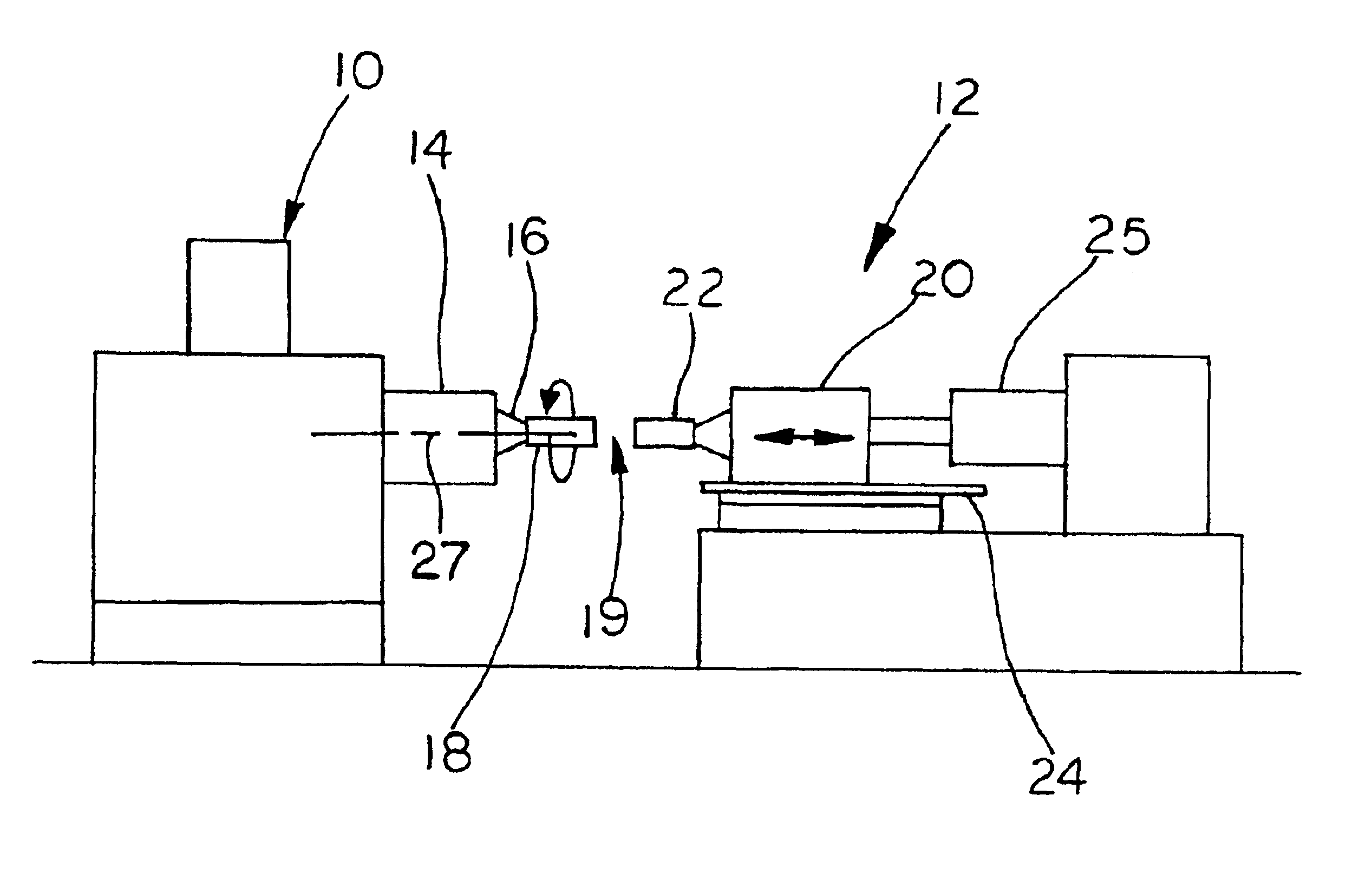
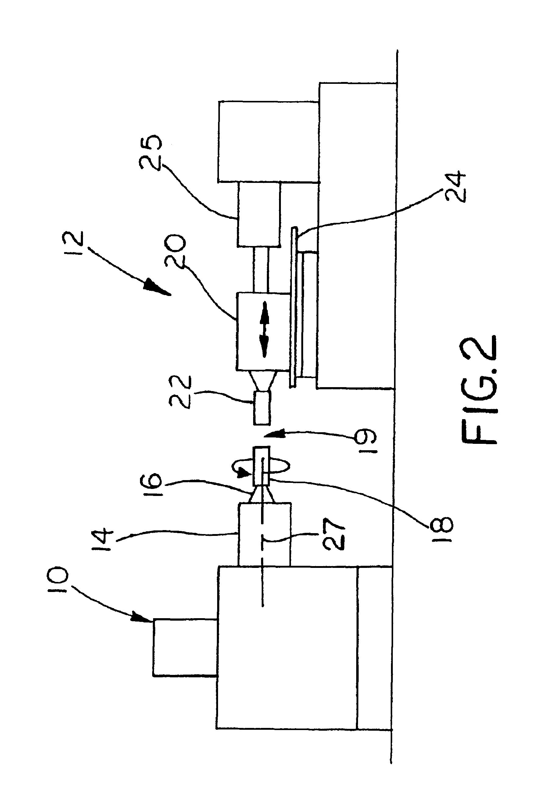
[0026]Referring now to the drawings, a control system for a friction welder according to the present invention is generally indicated by the reference numeral 10. Control system 10 is operatively connected to and controls the operation of a friction welding device 12. Friction welder 12 includes a rotating spindle 14, having a chuck assembly 16 for securing a first workpiece 18, and a non-rotating chuck assembly or tailstock 20 for holding a second workpiece 22. Typically, tailstock 20 is slidably mounted to a track or slide 24. An actuator 25 enables tailstock 20 holding second workpiece 22 to move towards spindle 14 holding first workpiece 18 in a direction parallel to the axis 27 of r...


PUM

PropertyMeasurementUnit
Nuclear radiationaaaaaaaaaa
Timeaaaaaaaaaa
Forceaaaaaaaaaa

Abstract

A method of friction welding first and second parts together at an angular orientation relative to each other includes the steps of mounting the first part in a spindle for axial rotation and the second part in a non-rotatable holder. The spindle is then rotated and the angular orientation of the first part relative to the second part is determined at any specific time. The holder is moved toward the spindle to bring the second part into frictional contact with the first part at a selected one of the specific times that the angular orientation is determined. Accordingly, due to frictional contact, the respective contacting surface of the parts are melted. The speed of the rotation of the spindle is then decreased and the holder is moved toward the spindle to forcibly urge the first and second parts together at the contacting surface. Rotation of the spindle is stopped at a specific determined angular orientation of the first part relative to the second part while continuing to forcibly urge the parts together to allow cooling and fused solidification of the contacting surfaces.

Description

CROSS-REFERENCE TO RELATED APPLICATION[0001]This is a continuation of application Ser. No. 60 / 038,332 filed Feb. 27, 1997.[0002]The present invention relates generally to a control system for use on friction welding machines for controlling the final angular orientation of two workpieces relative to each other that have been welded together using the friction welding process.APPENDIX[0003]A software computer program forming an appendix consisting of 5 pages is included as part of the specification.IDENTIFICATION OF COPYRIGHT[0004]A portion of the disclosure of this patent document contains material which is subject to copyright protection. The copyright owner has no objection to the facsimile reproduction by anyone of the patent document or the patent disclosure as it appears in the public Patent and Trademark Office patent file or records, but otherwise reserves all copyright rights whatsoever.BACKGROUND OF THE INVENTION[0005]Friction welding machines are generally well known in th...

Claims


Application Information

Patent Timeline
IPC IPC(8): B29C65/06B23K20/12B29C65/00
CPCB23K20/121B29C65/0672B29C66/90B29C66/93441B29C66/961B29C66/93451B29C66/9592B29C66/942B29C66/962B29C66/9231B29C66/9261B29C66/8322B29C66/92445
Inventor TULLY, LOWELL R.JOHNSON, STEPHEN A.KONIECZNY, DAVEESTES, STEPHEN R.
Owner SSD CONTROL TECH
Why Eureka
Try Eureka