Illumination assembly for dental and medical applications

a technology for illumination assemblies and dental and medical applications, applied in the direction of lighting support devices, spectales/goggles, optical radiation measurement, etc., can solve the problems of increasing the difficulty of viewing the patient or workpiece, the interior of such holes generally cannot be viewed without direct illumination, and the prior art devices fail to fully or partially include, etc., to achieve automatic illumination of the area the user is viewing, and the effect of reducing the weight of the illumination assembly

Inactive Publication Date: 2006-07-11
THE KERR
View PDF28 Cites 32 Cited by
  • Summary
  • Abstract
  • Description
  • Claims
  • Application Information

AI Technical Summary

Benefits of technology

[0020]Versatile attachment means for removably attaching the illumination assembly to the user's headgear (e.g., face shields, headbands, and eyeglasses, and associated lenses, loupes, and binoculars) allow the illumination assembly to be quickly fit to a wide variety of different types of headgear. The attachment means allows mounting of the illumination assembly in a position between the eyes of the user to provide coaxial in-line shadowless illumination of the operating site, and to automatically illuminate the area the user is viewing.
[0021]The illumination assembly is small, having a maximum dimension of approximately 1.8 inches without the attachment means and light guide, or approximately 1.6 inches when the housing is telescopically reduced to minimum length. By using only a single glass optical element within the housing and by remotely locating the illumination source, the weight of the illumination assembly is substantially reduced when compared to the illumination assemblies of the prior art. The weight is further reduced because there is no need for the heavy ceramic potting or reflective means that are required when the illumination source is located within the illumination assembly, and because a light guide having a small diameter is used. The weight of the illumination assembly without the attachment means and light guide is only approximately 8-10 grams when a plastic housing is used.
[0022]Due to its low weight, the illumination assembly is ideal for use with headgear such as face shields, headbands, and eyeglasses, and associated devices such as lenses, loupes, and binoculars, since it will not cause the headgear or associated devices to shift or fall from the user's head. Additionally, the illumination assembly is small enough in both diameter and length that it does not interfere with the user's binocular vision when mounted coaxially; it is virtually invisible to the user when mounted between the eyes. The light guide is small enough that it is unseen and virtually unfelt by the user, and its weight and stiffness will not cause the illumination assembly to inadvertently readjust or reposition against the user's wishes. Despite the small size of the light guide, its use does not decrease the illumination of the illumination assembly due to the high efficiency of the remainder of the assembly.

Problems solved by technology

However, there are certain characteristics which are desirable in head-mounted illumination assemblies and which the devices of the prior art fail to either partially or entirely include.
Otherwise, the user's hands, arms, or other objects may obstruct the light path and cast shadows upon the patient or workpiece and increase the difficulty in viewing the patient or workpiece.
Also, dentists and medical personnel often have a need to look into very small holes, such as holes drilled into teeth, and the interior of such holes generally cannot be viewed without direct illumination along the axis of the hole.
These devices have proven to be disadvantageous in that they can create a great deal of heat at a point close to the user's head, especially if high-intensity lightbulbs are used.
These devices can therefore be intensely uncomfortable to wear because they cause hot air to rise into the user's face when the user looks down, they cause perspiration from the user's forehead to drip into the user's eyes (and onto the patient or workpiece), and they can even cause burns to the user or patient when they grow hot enough.
Because the prior art illumination assemblies which mount a light source directly to the user's head are so uncomfortable, many devices instead use a light guide to transmit light from a remotely-located light source.
Many of the prior an illumination assemblies are not very versatile because they are permanently mounted within already existing headgear, such as the illumination devices of Cooley et al. and Price, which show eyeglasses with illumination elements at opposing sides of the eyeglass frames adjacent the support legs.
These devices can neither be used without the associated headgear nor repositioned to illuminate different areas of the patient or workpiece.
Additionally, if an illumination assembly is permanently affixed to headgear such as eyeglasses, headbands, face shields, etc., it is often difficult to use a second type of headgear in conjunction with the first type of headgear and the illumination assembly.
Fourth, since the illumination assembly may become contaminated with particles from the patient or workpiece or fluids splashing therefrom, the illumination assembly should be easy to clean.
The prior art illumination assemblies tend to be quite heavy due to their use of several optical elements (lenses, prisms, mirrors, etc.) and means for mounting these optical elements within the illumination assembly.
Due to the weight of the glass, the addition of even a single additional optical element tends to dramatically increase the weight of an illumination assembly.
Additionally, while the art is beginning to develop plastic lenses of high optical quality and lighter weight than glass lenses, these lenses are not preferred for use at exposed portions of the illumination assembly because they are more easily scratched, scuffed, or otherwise damaged during cleaning.
The weight of the illumination assembly can also create greater problems than discomfort.
It can make a substantial difference in its operability and safety of use, since a heavy illumination assembly can cause headgear to shift or even fall off the head.
This can be disastrous where the user's hands are performing an important medical procedure since the user may be forced to interrupt the procedure to readjust the binoculars, or else simply proceed and perform the procedure with impaired vision.
As another example, when the prior art illumination assemblies are mounted to eyeglasses, they tend to pull the eyeglasses off of the user's head if he or she looks downward.
Many of the prior art illumination assemblies have a large and awkward size, either due to their incorporation of internal illumination sources directly within the assembly or due to the requirements of the optics within the assembly.
Also, large illumination assemblies interfere with the user's binocular vision when mounted coaxially between the user's eyes.
The prior art illumination assemblies are also difficult to use when mounted coaxially, or when mounted to headgear in general, due to their use of bulky and heavy electrical or light guide cords.
These cords can bind and inhibit repositioning of illumination assemblies due to the stiffness of the cords, and they can also interfere with the user's binocular or peripheral vision.
Thick and heavy cords are also uncomfortable to wear when draped over or about the user's head, and they contribute to a feeling that the user is bound or “leashed” to the power supply or remote illumination source.
While the prior art illustrates smaller, lighter cords for supplying power or illumination to illumination assemblies, the smaller and lighter cords have the drawback that they cannot bear as much power or illumination to the illumination assemblies.
Thus, if the user wishes to obtain the advantages of a smaller cord, he or she is generally forced to settle for less illumination.
In particular, the prior art does not include an illumination assembly as described above suitable for attachment to and use with eyeglasses, headbands, or face shields in accompaniment with lenses, loupes, or binoculars associated with the eyeglasses, headbands, or face shields.

Method used


Image

  • Illumination assembly for dental and medical applications
  • Illumination assembly for dental and medical applications
  • Illumination assembly for dental and medical applications

Examples


Embodiment Construction

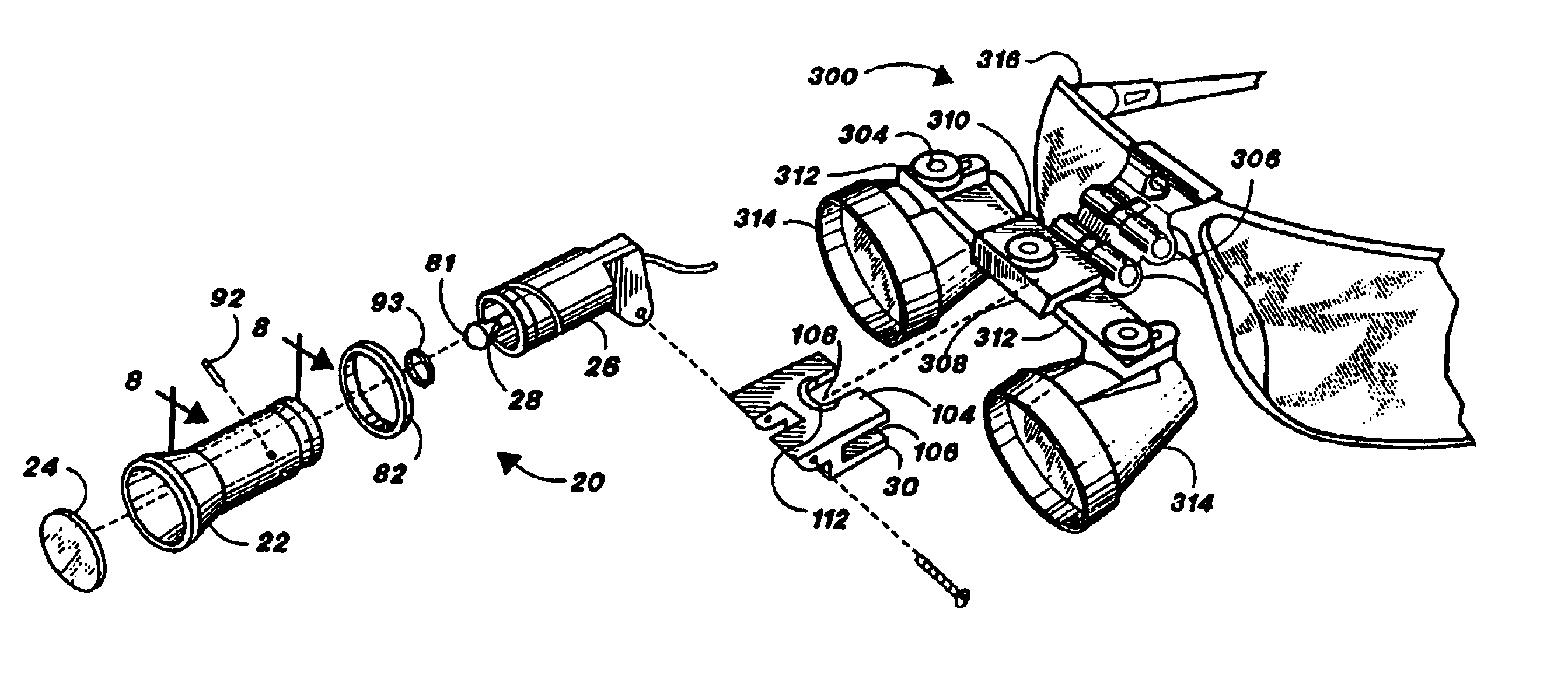
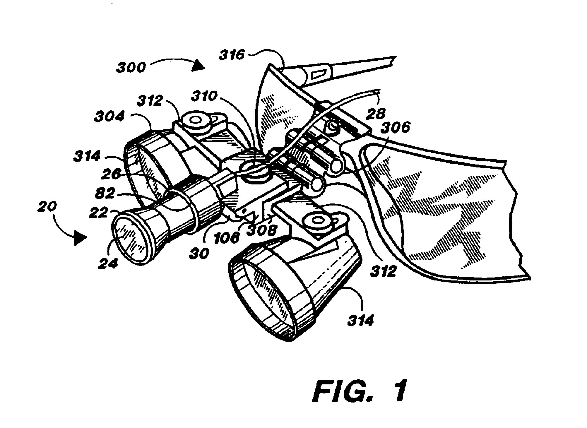
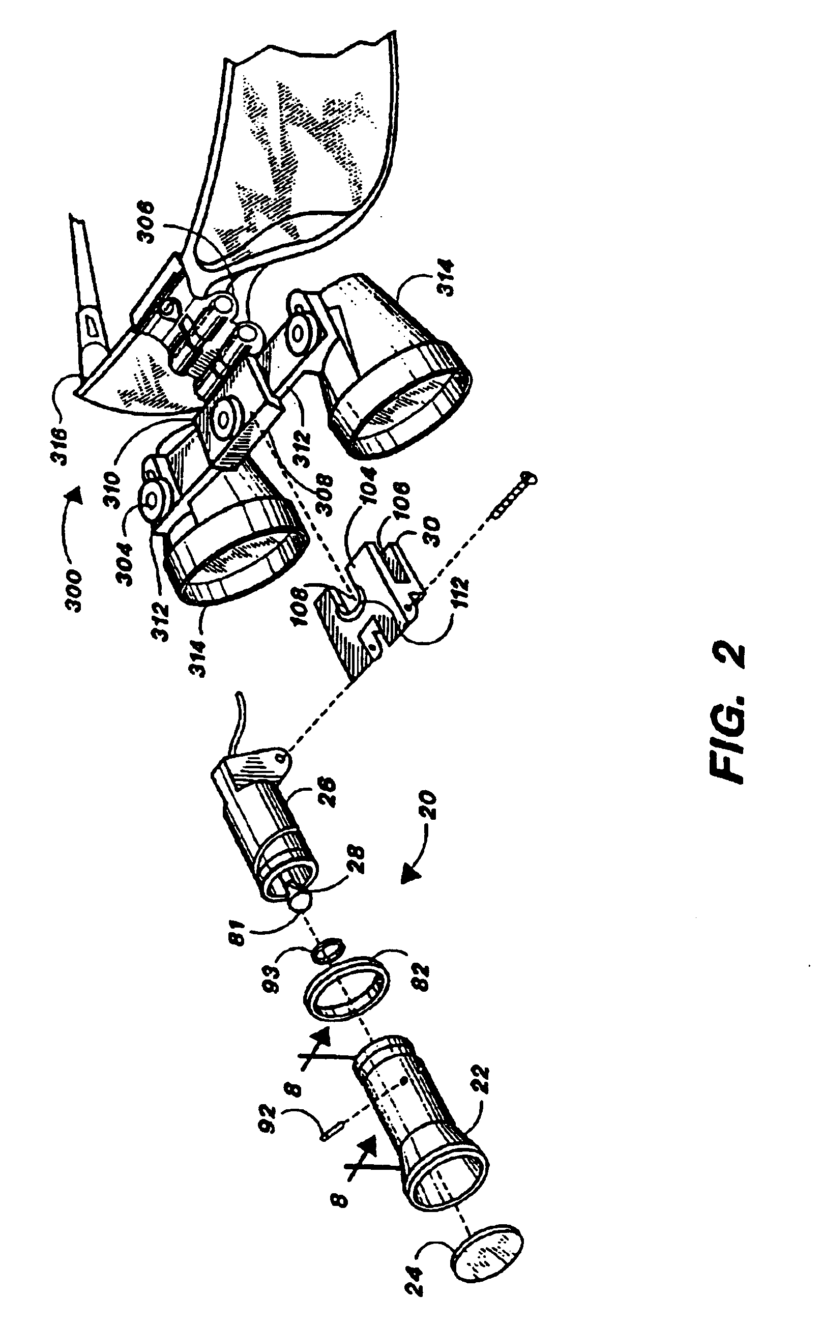
[0042]In the drawings, wherein the same or similar features are designated throughout with the same reference numeral, the illumination assembly of the present invention is shown at 20 in FIGS. 1-3. The illumination assembly 20 has five main components: a housing 22 which contains an optical element 24, a housing base 26 engaged to the housing 22 and wherein a light guide 28 enters, and a clip 30 which provides attachment means for removably attaching the housing base 26 to the user's head or headgear. Throughout this specification, when reference is made to attachment of the illumination assembly 20 to the user's head to headgear, this is understood to include attachment to implements mounted on the user's head such as eyeglasses and goggles, face shields and masks, and headbands and helmets, as well as similar implements. It is further understood to include attachment to accessory implements such as lenses, loupes, and binoculars mounted on the aforementioned implements. Each of t...


PUM


Abstract

A small, lightweight, high intensity illumination assembly for use in dental and medical applications. The illumination assembly includes attachment means for removable attachment to headgear such as eyeglasses, face shields, or headbands, and lenses, loupes, and binoculars associated with such headgear. The illumination assembly is able to achieve extremely light weight by using only a single optical element therein, e.g., an aspheric condensing lens, binary optical element, or holographic optical means, and by piping illumination to the optical element from a remote light source by use of a flexible light guide, e.g., a fiberoptic bundle.

Description

[0001]The present application is a reissue application of U.S. Pat. No. 5,667,291.FIELD OF THE INVENTION[0002]The invention relates generally to the field of head-mounted illumination devices for medical and dental use, and specifically to the field of small, lightweight, high-intensity illumination assemblies for medical and dental use which are mounted on the user's head to provide coaxial illumination.DESCRIPTION OF THE PRIOR ART[0003]Personnel who work in medical and dental fields frequently have a need to illuminate a portion of a patient or workpiece as they operate on the patient or workpiece. At the same time, they require the free use of their hands. Both of these needs are met by illumination assemblies known to the art which are mounted on the user's head or headgear and which illuminate the patient or workpiece. An example of such an apparatus can be found in U.S. Pat. No. 5,341,513 to Klein et al., which describes a headband whereupon a lamp is mounted.[0004]However, th...

Claims


Application Information

Patent Timeline
Patent Type & Authority Patents(United States)
IPC IPC(8): F21V21/084A61B17/00F21V8/00F21V21/088G02B25/02G02C7/08G02C11/04
CPCF21V21/084F21V21/145G02B6/0008G02B7/002G02B25/004G02C7/088G02C11/04G02C2200/02Y10S362/804
Inventor CAPLAN, CHARLES H.BUSHROE, FREDERICK N.
Owner THE KERR
Why Eureka
Try Eureka