Scanning phase measuring method and system for an object at a vision station

a phase measurement and vision station technology, applied in the direction of measuring devices, instruments, material analysis through optical means, etc., can solve the problem of not enough information available to do a phase calculation based on multiple buckets

Inactive Publication Date: 2008-01-01
ISMECA SEMICONDUCTOR HOLDING SA
View PDF35 Cites 8 Cited by
  • Summary
  • Abstract
  • Description
  • Claims
  • Application Information

AI Technical Summary

Benefits of technology

[0013]In carrying out the above objects and other objects of the present invention, a method is provided for high speed scanning phase measuring of an object at a vision station to develop physical information associated with the object. The method includes the steps of projecting a pattern of imagable electromagnetic radiation with at least one projector and moving the object relative to the at least one projector at the vision station to scan the projected pattern of electromagnetic radiation across a surface of the object to generate an imagable electromagnetic radiation signal. The method also includes the steps of receiving the imagable electromagnetic radiation signal from the surface of the object with a detector having a plurality of separate detector elements and maintaining the at least one projector and the detector in fixed relation to each other. Finally, the method includes the steps of measuring an amount of radiant energy in the received electromagnetic radiation signal wherein the detector elements produce images having different phases of the same scanned surface based on the measurement and computing phase values and amplitude values for the different phases from the images.

Problems solved by technology

A technique for capturing just one bucket image using a line scan camera is described in U.S. Pat. No. 4,965,665 but not enough information is available to do a phase calculation based on multiple buckets.

Method used


Image

  • Scanning phase measuring method and system for an object at a vision station
  • Scanning phase measuring method and system for an object at a vision station
  • Scanning phase measuring method and system for an object at a vision station

Examples


case 2

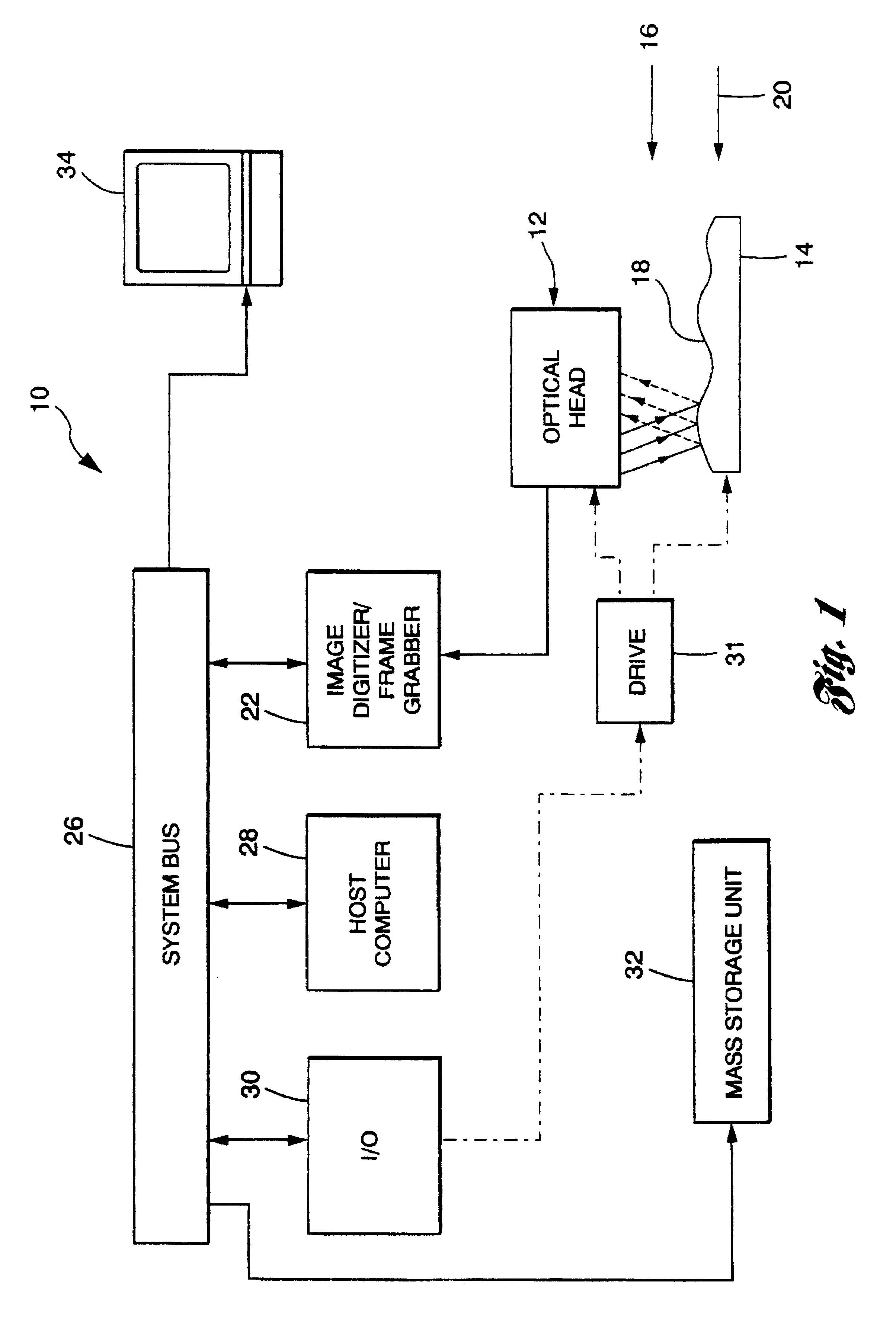
[0039 alluded to above would most likely use a CCD area array in the optical head 1 but could use a linear array or single point photodetector. In this case, as the surface 18 is moved toward or away from the optical head 12, images are taken as the phase of the projection changes. The analysis would consist of correcting for registration between images and then using the images to create the buckets needed for the phase calculation. If the camera images telecentrically or nearly telecentrically, then registration would not be required.

[0040]Systems that employ the Case 2 set-up have been described for use in white light interferometry systems as described in U.S. Pat. Nos. 5,398,113 and 5,355,221 but not for a moire (light stripe) application.

[0041]Although a method is described above for making phase calculations based on a moire (light stripe) system, the described technique could also be applied to any optical base phenomena where the phase is changed between the images created ...

first embodiment

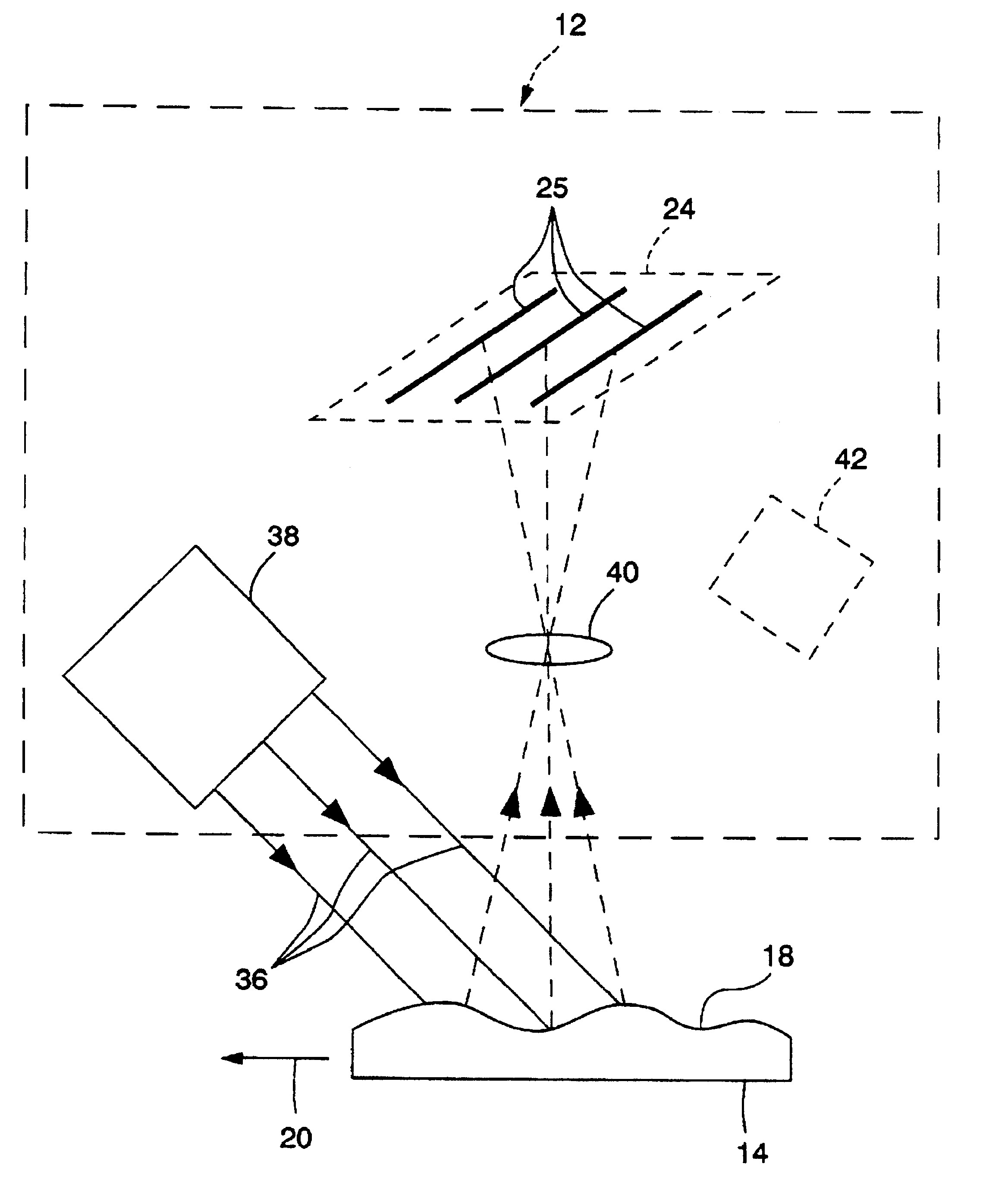
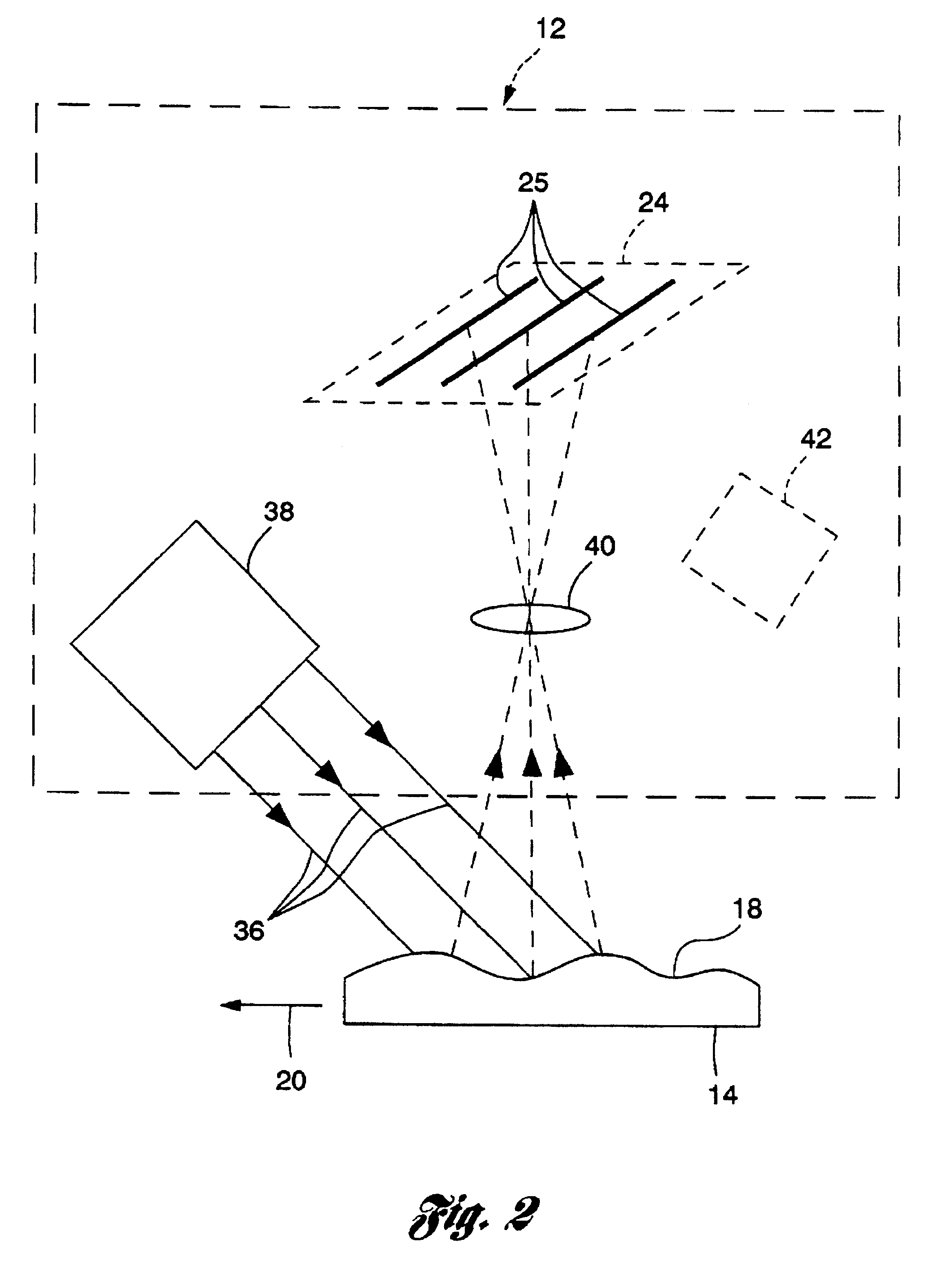
[0056]Referring again to the invention, the optical head 12 includes the light strip projector 28 and the camera includes the imaging lens 40 for focusing the scanned surface onto the trilinear array 24. The scanned surface is translated past the optical head 12 in the direction of the arrow 20. To eliminate perspective effects in both projection and imaging, the project and imaging system should be either telecentric or nearly telecentric. A nearly telecentric system is created by having the standoff from the optics being much larger than the measurement depth range.

[0057]For this discussion, the data from the first linear array in the detector is called b1 (for bucket 1). Likewise, the second and third linear arrays is called b2 and b3, respectively. The pitch of the projected light pattern creates a phase difference of ½ a cycle between b1 and b3. For each linear array, let b1(i,j), b2(i,j) and b3(i,j) designate the light intensity measurement for each linear array with j indicat...


PUM


Abstract

A method and system are provided including an optical head which moves relative to an object at a vision station to scan a projected pattern of imagable electromagnetic radiation across the surface of an object to be inspected at a relatively constant linear rate to generate an imagable electromagnetic radiation signal. In one embodiment, the electromagnetic radiation is light to develop dimensional information associated with the object. The optical head includes at least one projector which projects a grid of lines and an imaging subsystem which includes a trilinear array camera as a detector. The camera and the at least one projector are maintained in fixed relation to each other. Three linear detector elements of the array camera extend in a direction parallel with the grid of lines. The geometry of the optical head is arranged in such a way that each linear detector element picks up a different phase in the grid pattern. As the optical head is scanned across the surface of interest, the detector elements are continuously read out. Depth an each point on the surface is calculated from the intensity reading obtained from each of the detector elements that correspond to the same point on the surface. In this way, the phases of the pattern are calculated from the three intensity readings obtained for each point. In another embodiment, the imagable electromagnetic radiation is polarized and the response of the detector elements is polarization sensitive. The generated images are based on polarization for the surface.

Description

CROSS-REFERENCE TO RELATED APPLICATION[0001]This application is related to U.S. patent application entitled “Optical Measuring System” filed Jun. 17, 1994 and having U.S. Ser. No. 08 / 262,130.TECHNICAL FIELD[0002]This invention relates to non-invasive measuring methods and systems and, in particular, to scanning phase measuring methods and systems for an object at a vision station.BACKGROUND ART[0003]Height distribution of a surface can be obtained by projecting a light stripe pattern onto the surface and then reimaging the light pattern that appears on the surface. A powerful technique for extracting this information based on taking multiple images (3 or more) of the light pattern that appears on the surface while shifting the position (phase) of the projected light stripe pattern is referred to as phase shifting interferometry as disclosed in U.S. Pat. Nos. 4,641,972 and 4,212,073.[0004]The multiple images are usually taken using a CCD video camera with the images being digitized a...

Claims


Application Information

Patent Timeline
Patent Type & Authority Patents(United States)
IPC IPC(8): G01B11/24G01B11/25
CPCG01B11/2522
Inventor BIEMAN, LEONARD H.
Owner ISMECA SEMICONDUCTOR HOLDING SA
Why Eureka
Try Eureka