Treatment of presbyopia and other eye disorders using a scanning laser system

a scanning laser and presbyopic technology, applied in the field of presbyopic treatment and the treatment and prevention of glaucoma using dual, can solve the problems of inability to present details or practical methods or laser parameters for presbyopic correction, mechanical approaches have drawbacks of complexity and time consumption, and prior art laser parameters do not present details or practical methods for presbyopic correction, so as to prevent bleeding, effectively ablate the sclera tissue, and prevent the bleeding

Inactive Publication Date: 2008-01-15
SURGILIGHT
View PDF56 Cites 34 Cited by
  • Summary
  • Abstract
  • Description
  • Claims
  • Application Information

AI Technical Summary

Benefits of technology

[0015]It is yet another preferred embodiment of the present invention to provide a scanning mechanism to effectively ablate the sclera tissue at a controlled depth by beam overlapping.
[0016]It is yet another preferred embodiments of the present invention to provide an apparatus and method such that both the ablative and the coagulative lasers can have applied to their beams the corneal surface to thereby prevent bleeding during the procedure.
[0017]It is yet another embodiment of the present invention to provide an integration system in which a coagulative laser may have the beam delivered by a scan or by a fiber-coupled device which can be manually scanned over the cornea. It is yet another embodiment of the present invention to focus the laser b...

Problems solved by technology

The above-described prior arts are however limited to the use of reshaping the corneal surface curvature for the correction of myopia and hyperopia.
These mechanical approaches have the drawbacks of complexity and are time consuming, costly and have potential side effects.
However, these prior arts do not present any details or practical methods or laser parameters for the presbyopic corrections.
No clinical studies have been practiced to show the effectiveness of t...

Method used


Image

  • Treatment of presbyopia and other eye disorders using a scanning laser system
  • Treatment of presbyopia and other eye disorders using a scanning laser system
  • Treatment of presbyopia and other eye disorders using a scanning laser system

Examples


Embodiment Construction

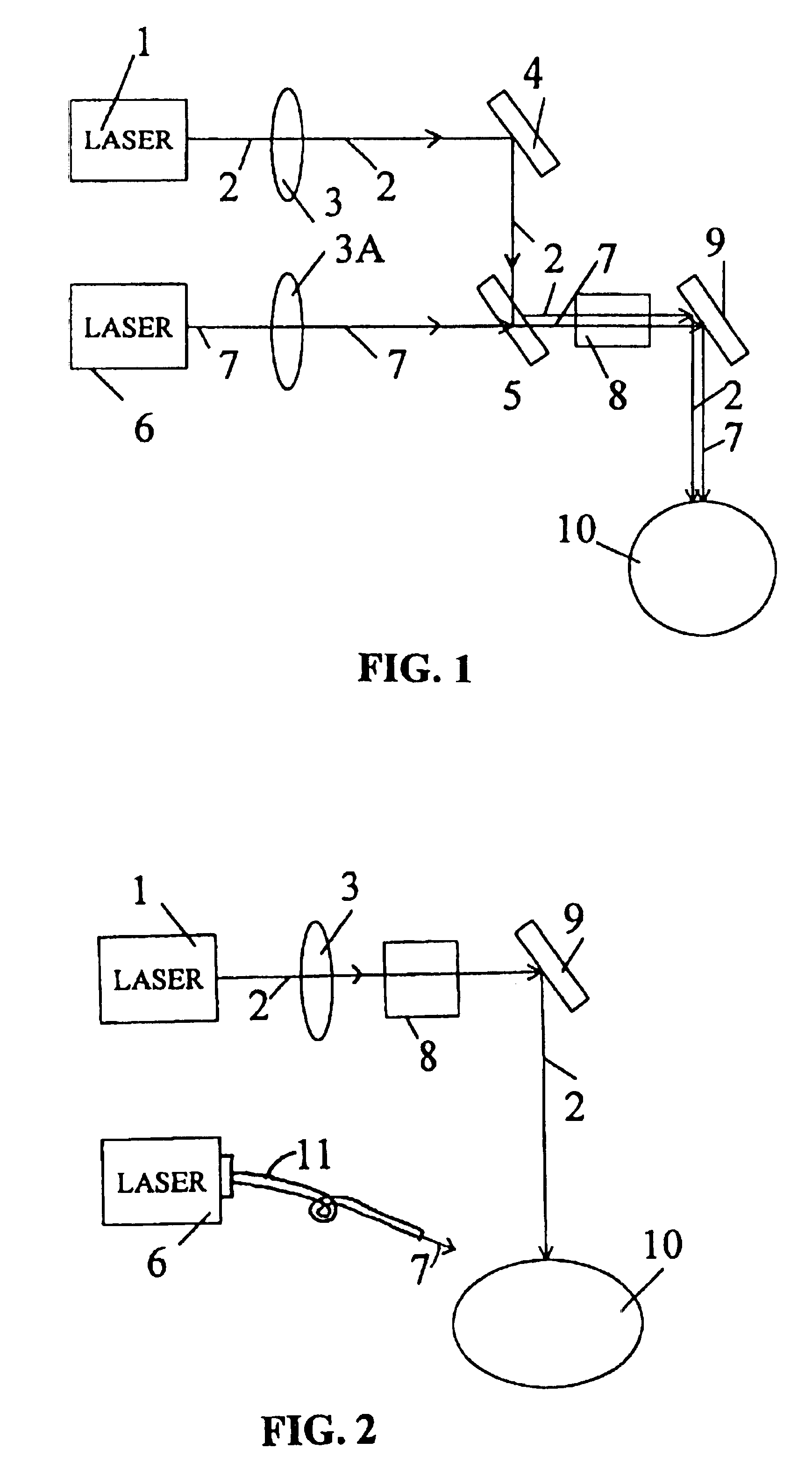
[0026]FIG. 1 of the drawings is a schematic of a laser system having an ablative laser 1 producing a laser beam 2 of a predetermined wavelength and focused by a lens 3 onto a reflecting mirror 4 which is coupled to another reflecting mirror 5. The system also consists of a coagulation laser 6 having a laser beam 7 of a predetermined wavelength focused by a lens 3A through a mirror 5. The ablation laser 1 beam 2 and the coagulation laser 6 beam 7 are directed onto a scanner 8. The beams 2 and 7 are then reflected by a mirror 9 onto the cornea 10 of a patient's eye. The scanner 8 consists of a pair of motorized coated mirrors with a 45 degree highly reflecting both the ablative laser beam 2 and the coagulative laser beam 7. The mirror 4 and mirror 9 are highly reflective to the wavelength of the beams 2 and 7. Mirror 5 is coated such that it is highly reflective of laser beam 2 but highly transparent to laser beam 7. The focusing lens 3 has a focal length of about 10-100 cm such that ...


PUM


Abstract

Presbyopia is treated by a method which uses ablative lasers to ablate the sclera tissue and increase the accommodation of the ciliary body. Tissue bleeding is prevented by an ablative laser having a wavelength of between 0.15 and 3.2 micron. A scanning system is proposed to perform various patterns on the sclera area of the cornea to treat presbyopia and to prevent other eye disorder such as glaucoma. Laser parameters are determined for accurate sclera expansion.
REEXAMINATION RESULTS
The questions raised in reexamination request no. 90/006,090, filed Aug. 22, 2001, have been considered and the results thereof are reflected in this reissue patent which constitutes the reexamination certificate required by 35 U.S.C. 307 as provided in 37 CFR 1.570(e), for ex parte reexaminations, or the reexamination certificate required by 35 U.S.C. 316 as provided in 37 CFR 1.997(e) for inter partes reexaminations.

Description

BACKGROUND OF THE INVENTION[0001]1. Field of the Invention[0002]The present invention relates to methods and apparatus for the treatment of presbyopia and the treatment and prevention of glaucoma using dual-beam scanning lasers.[0003]2. Prior Art[0004]Corneal reshaping, including a procedure called photorefractive keratectomy (PRK) and a new procedure called laser assisted in situ keratomileusis, or laser intrastroma keratomileusis (LASIK), has been performed by lasers in the ultraviolet (UV) wavelength of 193-213 nm. Commercial UV refractive lasers include ArF excimer lasers at 193 nm and other non-excimer, solid-state lasers, such as the one patented by the present inventor in 1992 (U.S. Pat. No. 5,144,630). Precise, stable corneal reshaping requires lasers with strong tissue absorption (or minimum penetration depth) such that the thermal damage zone is at a minimum (less than few microns). Furthermore, accuracy of the procedure of vision correction depends on the amount of tissue...

Claims


Application Information

Patent Timeline
IPC IPC(8): A61B19/00A61F9/007A61F9/01
CPCA61F9/00781A61F9/008A61F9/00808A61F9/00838A61F2009/00865A61F2009/00872
Inventor LIN, JUI-TENG
Owner SURGILIGHT
Why Eureka
Try Eureka