Latch-up recovery in quantized feedback DC restorer circuits

a quantized feedback and restorer technology, applied in pulse technique, dc level restoring means or bias distort correction, baseband system details, etc., can solve the problems of circuits being susceptible to latching up, requiring supplementary circuitry, and loss of low frequency and dc components in received data

Inactive Publication Date: 2008-01-29
GENNUM CORP
View PDF11 Cites 13 Cited by
  • Summary
  • Abstract
  • Description
  • Claims
  • Application Information

AI Technical Summary

Benefits of technology

[0006]In one aspect, the present invention is a circuit for receiving an input signal and providing a quantized output signal in response, said quantized output signal being at either a first level or a second level, and said input signal being substantially at either said first level or said second level, said circuit comprising: (a) an automatic gain control (AGC) circuit for providing a gain signal which processes said input signal to output a controlled signal having a constant amplitude at either said first level or said second level, said AGC circuit being operative in a first mode to provide said gain signal in response to the difference between the level of said controlled signal and the level of said quantized output signal; (b) a restorer circuit coupled to said AGC circuit for receiving said controlled signal and for providing a quantized output signal in response; (c) a carrier detect circuit coupled to said AGC circuit and having an input for receiving said quantized output signal, said carrier detect circuit providing a detection signal for indicating the presence of a transition in the level of said quantized output signal, said detection signal being coupled to said AGC circuit; such that during periods when said detection signal indicates that there are transitions in the level of said quantized output signal, said AGC circuit is operative in said first mode, and during periods when said detection signal indicates that there are no transitions in the level of said quantized output signal, said AGC circuit is operative in a second mode wherein said gain signal is continually increased, at least to a predetermined level.

Problems solved by technology

This results, among other things, in a loss of the low frequency and DC components in the received data.
A QFB DC restorer circuit generally exhibits superior noise and jitter performance, however such circuits are susceptible to latching-up if the output of the restorer is in the incorrect state at the onset of data transmission.
Prior art methods of overcoming the latch-up problem involve additional start-up circuitry and / or deviations in the QFB structure, and, as a result, require supplementary circuitry and exhibit inferior circuit performance.

Method used


Image

  • Latch-up recovery in quantized feedback DC restorer circuits
  • Latch-up recovery in quantized feedback DC restorer circuits
  • Latch-up recovery in quantized feedback DC restorer circuits

Examples


Embodiment Construction

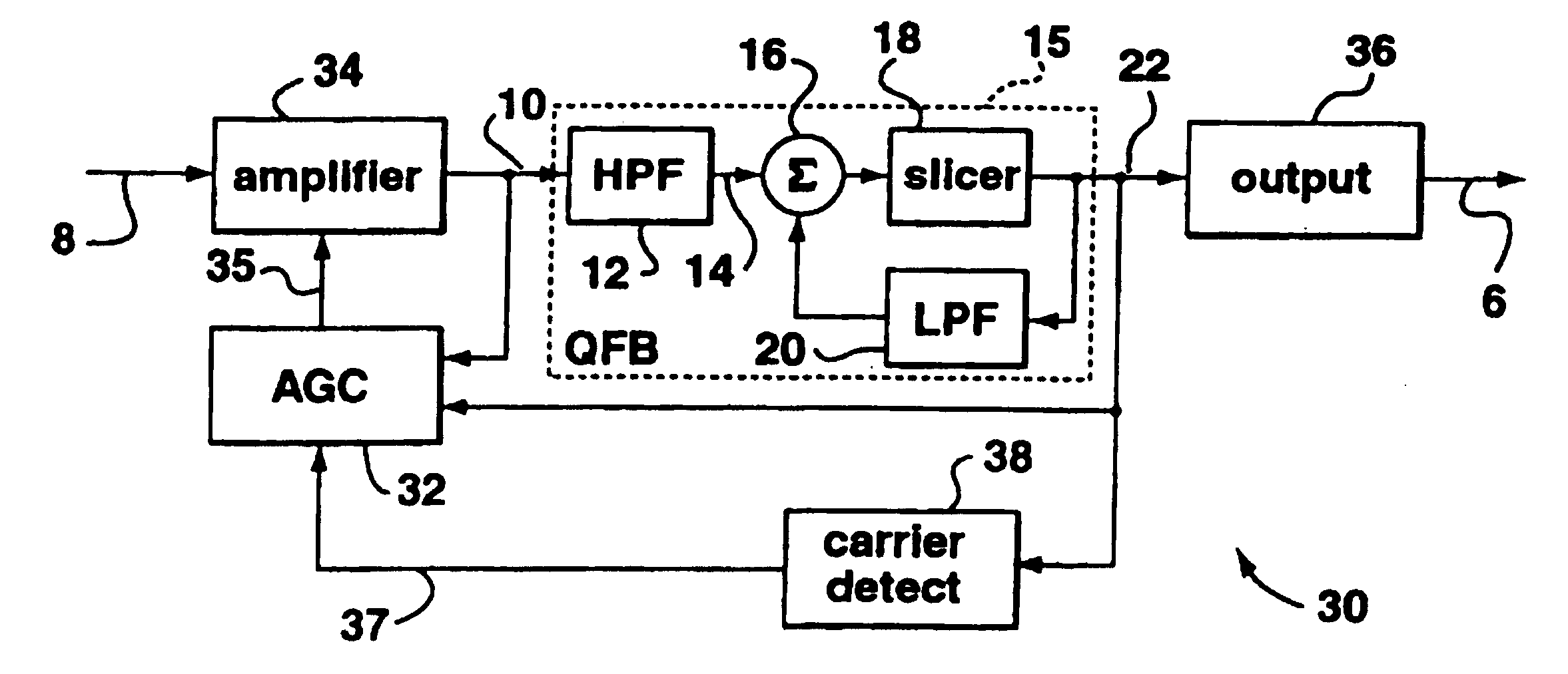
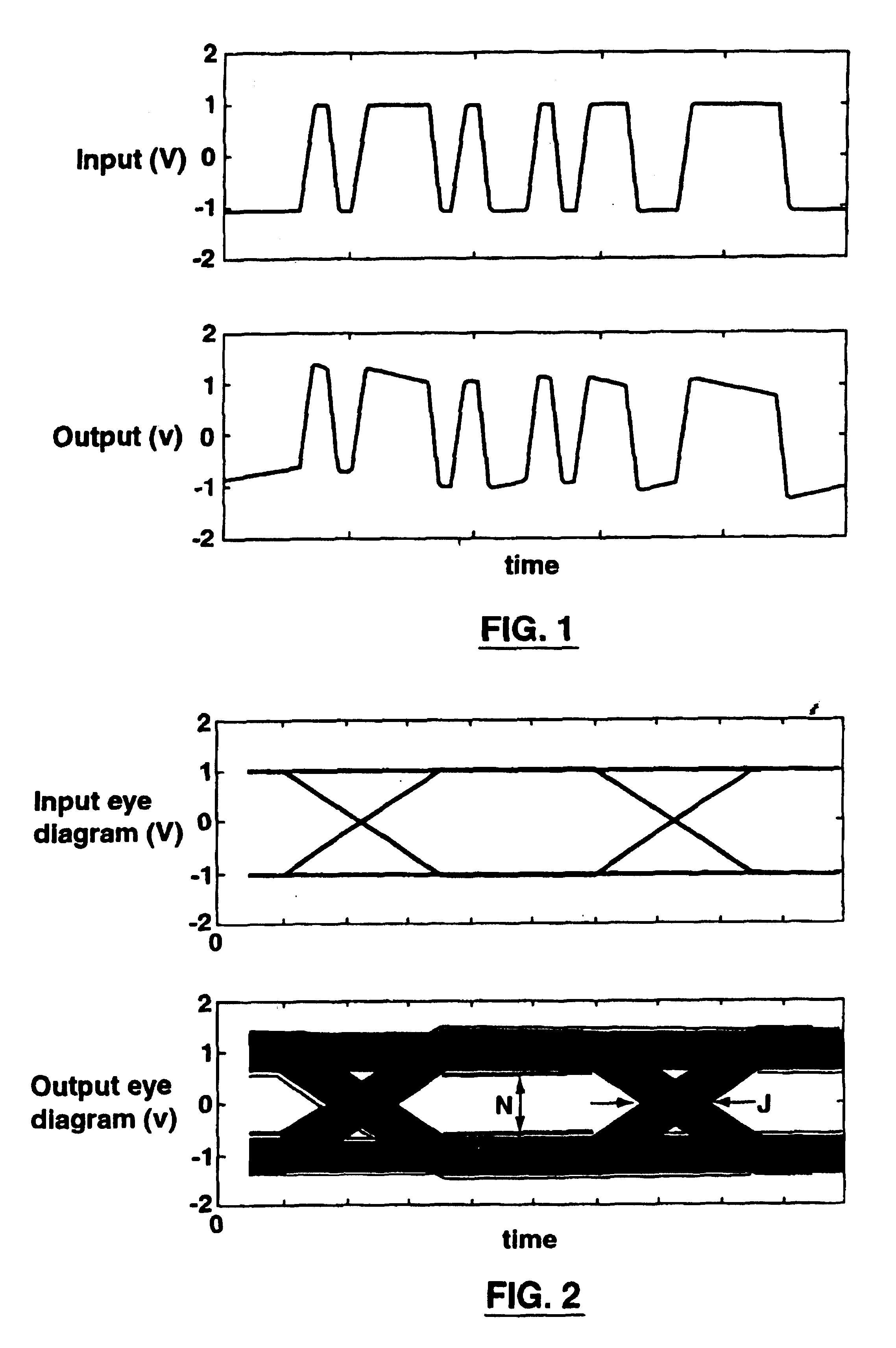
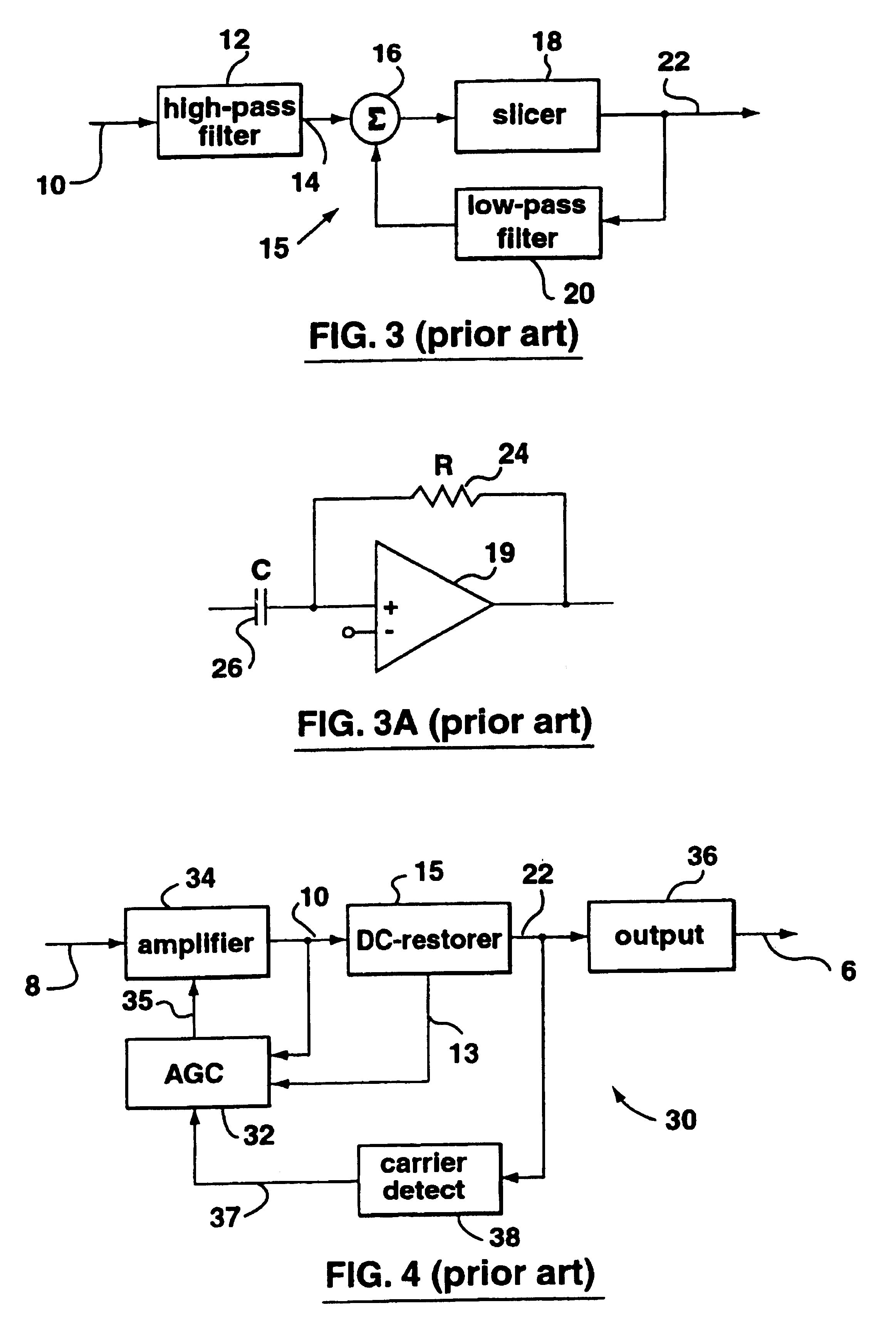
[0029]In a serial digital data communication system, when the signal passes through a high-pass filter (such as an AC-coupling network which, for example, might be present between a transmitter and a transmission line) it loses its low-frequency components and experiences the “zero-wander” effect. Zero wandering is illustrated in FIG. 1, and can cause serious problems in signal detection since the effective zero of the signal (defined as the signal zero crossing) drifts. As a result of this drift, the noise margin is reduced. Furthermore, in the presence of non-zero rise and fall times in the signal, which are always present in practice, the drift in zero crossing translates into timing jitter and closes the eye diagram (i.e decreases the noise margin) of the signal. FIG. 2 illustrates the concepts of noise margin N and jitter J in a data communication system, in terms of the input and output eye diagrams.

[0030]To overcome the aforementioned problems, the lost low-frequency componen...


PUM


Abstract

A method and apparatus for avoiding and or recovering from the latch-up condition in a quantized feedback DC restorer circuit for use in a digital data communication system receiver. An automatic gain control (AGC) circuit controls the level of the received data by comparing the AGC output with a quantized output signal from the DC restorer. A carrier detect circuit detects the presence of data transitions in the quantized output signal, and in the absence of such transitions continuously ramps up the gain of the AGC until such transitions are detected. The carrier detect circuit can be further used to disable, either entirely or partially, the positive feedback path of the DC restorer in the absence of transition in the quantized output signal. The present invention further provides an inherent muting function of the DC restorer output signal in the absence of valid data transitions.

Description

FIELD OF THE INVENTION[0001]The present invention relates to the field of serial digital data communication systems. In particular, the present invention relates to latch-up avoidance and recovery in a serial digital data receiver using a quantized feedback DC restorer.BACKGROUND OF THE INVENTION[0002]In a digital data communication system the transmitted data is generally attenuated and distorted by the medium and the AC coupling networks through which it is transmitted. This results, among other things, in a loss of the low frequency and DC components in the received data.[0003]To combat this problem, receivers typically include a DC (direct current) restorer to restore or regenerate the low frequency and DC components of the transmitted input, and an automatic gain control (AGC) circuit which automatically changes the gain or amplification of the received input to maintain the level of the amplified signal essentially constant despite variations in input signal strength.[0004]DC ...

Claims


Application Information

Patent Timeline
Patent Type & Authority Patents(United States)
IPC IPC(8): H04L25/10H04L27/08H04L25/06
CPCH04L25/063
Inventor SHAKIBA, MOHAMMAD HOSSEIN
Owner GENNUM CORP
Why Eureka
Try Eureka