Extended source transmitter for free space optical communication systems

a technology of optical communication system and transmitter, applied in the field of free space optical communication system, can solve the problems of reducing the transmission power of optical signals through free space, affecting the quality of optical signals, so as to achieve the effect of increasing the transmission power of a given laser product classification

Inactive Publication Date: 2013-09-03
OL SECURITY LIABILITY CO
View PDF16 Cites 0 Cited by
  • Summary
  • Abstract
  • Description
  • Claims
  • Application Information

AI Technical Summary

Benefits of technology

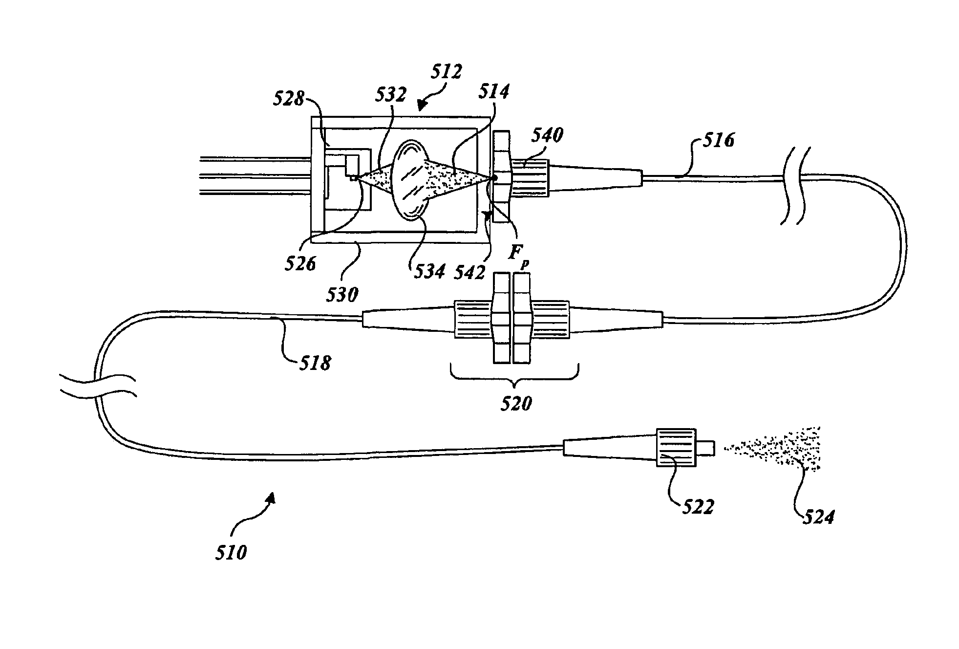
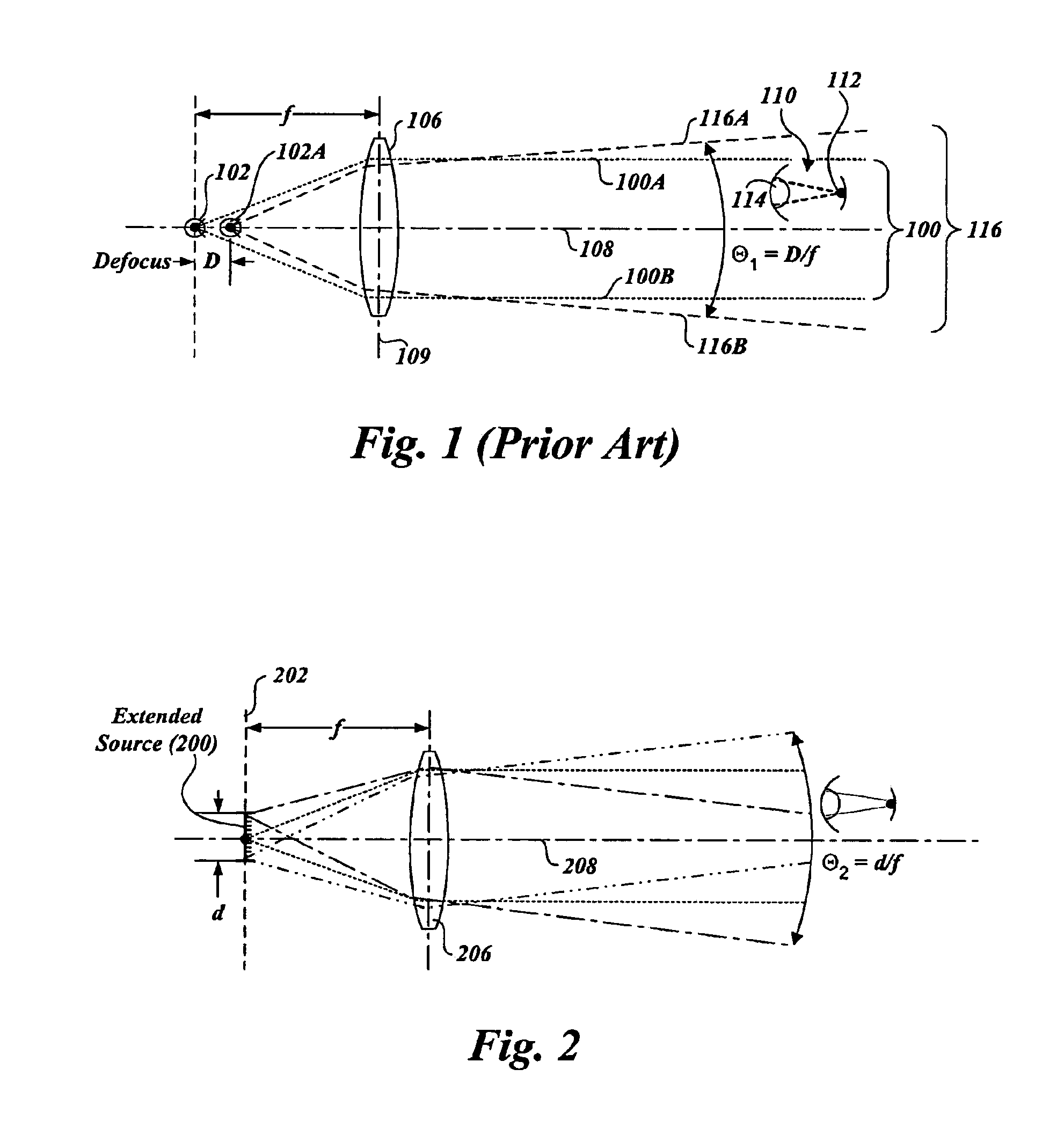
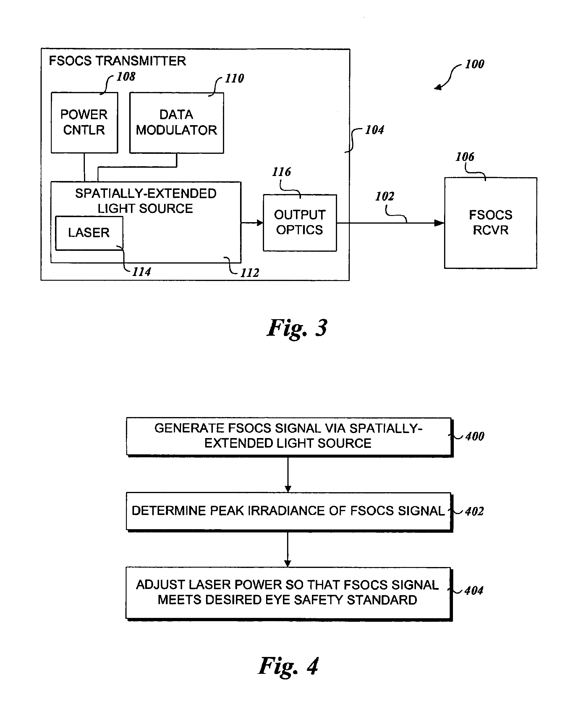
[0007]According to aspects of the present invention, an apparatus and method is provided for generating a FSOCS optical signal via a spatially-extended light source. In one embodiment, the spatially-extended light source is in the form of a mode-scrambled optical fiber light distribution and the transmitter employs single-aperture optics. An optical beam having a “top hat” intensity profile is produced, which provides several advantages. One of these advantages is the transmitter power for a given laser product classification may be increased while still satisfying peak irradiance limits defined for eye safety.

Problems solved by technology

As network demands continue to increase, existing network infrastructures and technologies are reaching their limits.
Transmission of optical signals through free space poses many challenges.
Notably, atmospheric conditions can greatly degrade signal strength, and consequently, reduce the maximum link distances.
Also, when launching a single-mode beam from a free-space optical terminal using conventional means, atmospheric scintillation and other wavefront distortion cause the beam to break up into chaotic bright and dark spots.
In some FSOCS applications, non-uniform power distributions far from the transmitter tend to undesirably limit the permissible overall power of the optical signal because the peak possible irradiance must meet specified eye safety standards.

Method used


Image

  • Extended source transmitter for free space optical communication systems
  • Extended source transmitter for free space optical communication systems
  • Extended source transmitter for free space optical communication systems

Examples


Embodiment Construction

[0023]Embodiments of an apparatus and method for generating mode-scrambled optical signals are described herein. In the following description, numerous specific details are disclosed to provide a thorough understanding of embodiments of the invention. One skilled in the relevant art will recognize, however, that the invention can be practiced without one or more of the specific details, or with other methods, components, materials, etc. In other instances, well-known structures, materials, or operations are not shown or described in detail to avoid obscuring aspects of the invention.

[0024]Reference throughout this specification to “one embodiment” or “an embodiment” means that a particular feature, structure, or characteristic described in connection with the embodiment is included in at least one embodiment of the present invention. Thus, the appearances of the phrases “in one embodiment” or “in an embodiment” in various places throughout this specification are not necessarily all ...


PUM


Abstract

An apparatus for transmission of free space optical communication system signals employing a spatially-extended light source and method of using the same. A laser beam source directs an optical signal into a free end of a segment of multimode fiber. As the optical signal passes through the segment of multimode fiber, the optical signal is converted into a mode-scrambled optical signal. This mode-scrambled signal may then be used as a spatially-extended light source that is directed outward as an optical beam through the use of a collimating lens.

Description

CROSS REFERENCE TO RELATED APPLICATIONS[0001]The present applicationThis is a Reissue application of U.S. Ser. No. 10 / 681,552, filed Oct. 7, 2003, now U.S. Pat. No. 7,072,543, granted Jul. 4, 2006, which is a continuation-in-part of U.S. patent application Ser. No. 10 / 128,953 filed Apr. 22, 2002, now U.S. Pat. No. 6,810,175, entitled “Off-Axis Mode Scrambler” by Jun Shan Wey et al., which is incorporated herein by reference. The present invention is also related to U.S. patent application Ser. No. 09 / 886,248 filed Jun. 20, 2001, entitled “Multimode Optical Signal Transmission in a Free-Space Optical Communication System” by Mark Lewis Plett.FIELD OF THE INVENTION[0002]The present invention generally relates to free-space optical communications systems (FSOCSs), and, more specifically, to a method and apparatus for increasing laser output power while maintaining compliance with eye safety standards.BACKGROUND INFORMATION[0003]With the increasing popularity of wide area networks (WAN5...

Claims


Application Information

Patent Timeline
Patent Type & Authority Patents(United States)
IPC IPC(8): G02B6/26G02B6/42
CPCG02B6/421G02B6/14G02B6/4204
Inventor PIERCE, ROBERT M.BELL, JOHN A.SJAARDA, CARRIE JEANRUSH, DAVID
Owner OL SECURITY LIABILITY CO
Why Eureka
Try Eureka