
System for treating solid discharge filth

A technology for treating system and dirt, applied in the direction of using liquid separation agent, dispersed particle separation, chemical instruments and methods, etc., can solve the problems of high use cost, lack of clean air, large investment cost, etc. The effect of low cost, simple structure and reduced investment cost

Inactive Publication Date: 2007-08-29
汤荣康
View PDF5 Cites 0 Cited by
  • Summary
  • Abstract
  • Description
  • Claims
  • Application Information

AI Technical Summary

Problems solved by technology

However, due to the high cost of production and use of many purification devices at present, it is unacceptable for each emission unit to cause the current common situation - on the one hand, good air is needed, and on the other hand, due to the high investment cost of environmental protection equipment, people have to to clean air

Method used


Image

  • System for treating solid discharge filth
  • System for treating solid discharge filth

Examples


Embodiment Construction

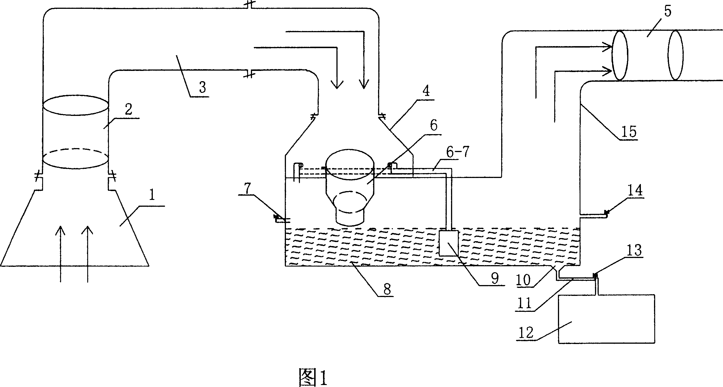
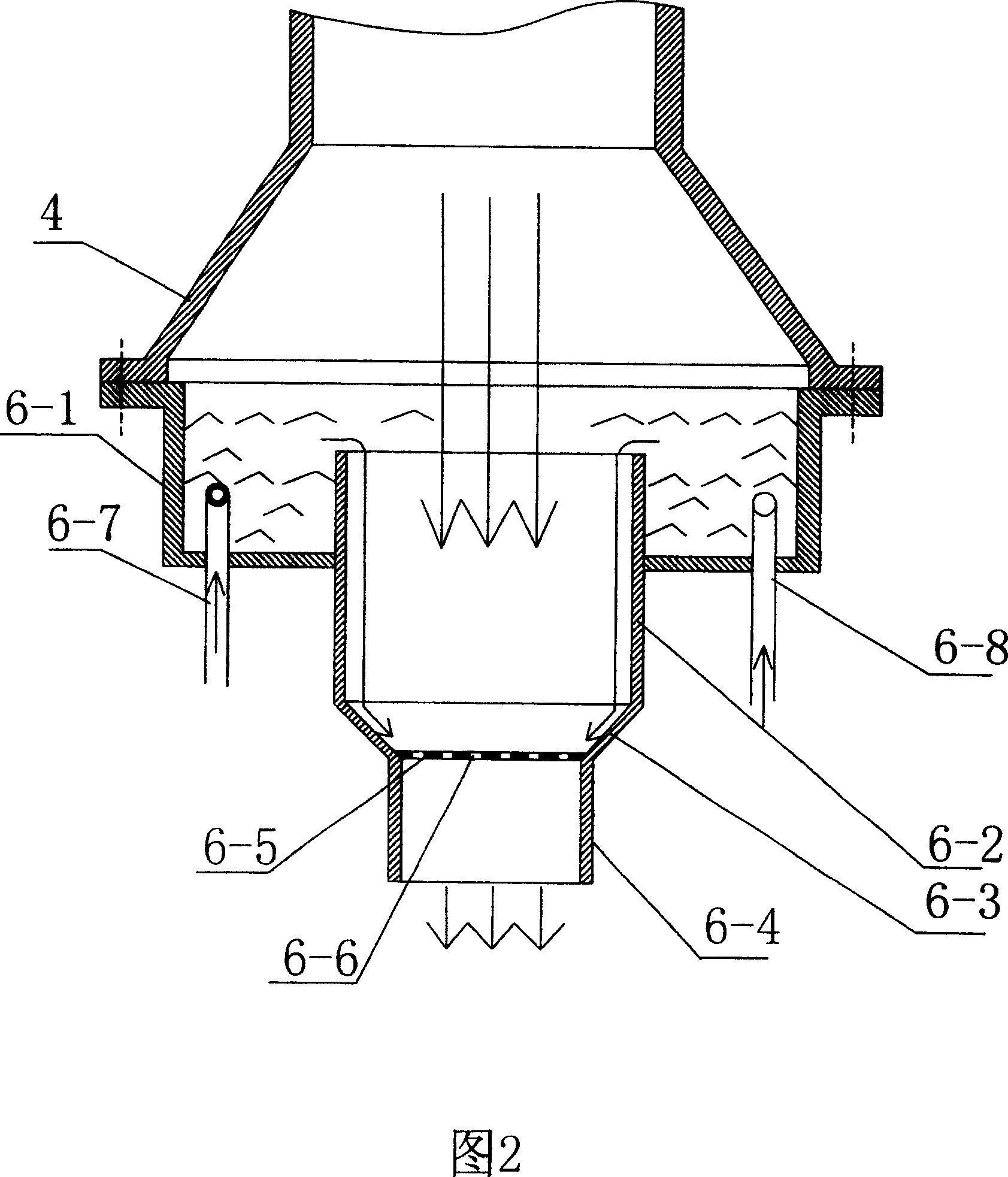
[0015] The atomization device 6 includes a water collecting pan 6-1 arranged between the delivery pipeline 3 and the sewage tank 8, two water inlet pipes 6-7 and 6-8 are arranged in the water collecting tray 6-1, and two water inlet pipes The ends of 6-7 and 6-8 are arranged in the tangential direction of the water collecting tray 6-1, and the water outlet direction is arranged forward. A through mixing cylinder is arranged in the water collection tray 6-1. The mixing cylinder is composed of two large and small cylinders 6-2 and 6-4. The two cylinders are transitionally connected by a conical cylinder 6-3. , Weld the horizontal dividing plate 6-5 that all opens circular through hole 6-6 on the connecting surface of conical cylinder 6-3 and lower cylinder 6-4.

[0016] The conveying pipeline 3 is connected between the dirt collecting chamber 1 and the atomizing device 6, the exhaust fan 2 is arranged in the conveying pipeline 3, the atomizing device 6 is connected to the upper ...


PUM


Abstract

A system relates to environmental equipment decontaminating deleterious gas. It comprises feculence collection chamber, transportation tube, pulverization device, sinkhole and dispelling tube. The transportation tube is between feculence collection can and pulverization device, sinkhole is on the pulverization device and dispelling tube is on the dispelling tube. The decontamination effect arrives more than 90%. The decontamination equipment is high-efficiency and energy-abstemious. It is used in the industry of environmental protect, spray-paint room, boiler, spinning and weaving, chemical plant, smelt, casting and mess hall.

Description

technical field [0001] The invention relates to an environmental protection equipment, in particular to a purification treatment device for fine solid dirt, such as dust and other harmful gases. Background technique [0002] During industrial production or civil life processing, a large amount of dust and harmful substances are often discharged into the atmosphere. This kind of hazard has been hated by people because they directly endanger people's living environment. accepted by people. However, due to the high cost of production and use of many purification devices at present, it is unacceptable for each emission unit to cause the current common situation - on the one hand, good air is needed, on the other hand, due to the high investment cost of environmental protection equipment, people have to to clean air. This not only affects people's lives, but also brings long-term hidden dangers to our future generations. Contents of the invention [0003] The purpose of the ...

Claims


Application Information

Patent Timeline
Patent Type & Authority Patents(China)
IPC IPC(8): B01D47/00
Inventor 汤荣康
Owner 汤荣康
Learn More