M Chi N Chi K optical switch array suitable to whole optical network and its method

An optical switch array, wavelength-selective technology, applied in the field of integrated optics, can solve the problems of fixed structure, high cost, inconvenient optical amplification, etc., and achieve the effect of small device size and low loss

Inactive Publication Date: 2008-02-13
李志扬
View PDF7 Cites 2 Cited by
  • Summary
  • Abstract
  • Description
  • Claims
  • Application Information

AI Technical Summary

Problems solved by technology

The advantage of using this method to construct a large optical switch array is that there is no crossover of optical waveguides on the same chip, which overcomes the mutual crosstalk caused by crossover of optical waveguides. The disadvantage is that the structure is fixed, lacks flexibility, and is not easy to insert buffer channels. It is also not easy to achieve optical amplification, so the necessary functions of the optical switching system, such as optical buffering and optical amplification, can only be realized by other special devices, which further increases the complexity and cost of the system
In addition, the AWG-based 1×N optical switch array is connected in series with an optical switch after each output channel of the AWG. Since the light waves of each wavelength from the input optical waveguide are dispersed into N output channels, this switch is destructive. Sexual, that is, either let the optical signal pass through or lose it, which is not convenient for passing to the next level for processing
At the same time, since the corresponding relationship between each wavelength light wave of each input channel of the AWG and the output optical waveguide is fixed, to implement optical routing with the AWG, wavelength conversion must be performed, and a wavelength converter is equipped for each wavelength of each channel. Very big
And arrayed waveguide interferometer (invention patent application number: 01114223.5, PCT application number: PCT / CN02 / 000340, utility model patent number: ZL01240150.1) and wavelength selector (invention patent application number: 03122029.0) are proposed by the inventor recently Two new types of optical passive devices, how to use them to construct a large optical switch array has not been specifically proposed in the published literature
Therefore, the existing technology and literature have not yet provided a large-scale optical switch array technology solution suitable for all-optical networks, with high wavelength selectivity and strong comprehensive functions, so it is also difficult to use a chip to achieve all-optical routing.

Method used


Image

  • M Chi N Chi K optical switch array suitable to whole optical network and its method
  • M Chi N Chi K optical switch array suitable to whole optical network and its method
  • M Chi N Chi K optical switch array suitable to whole optical network and its method

Examples


Embodiment Construction

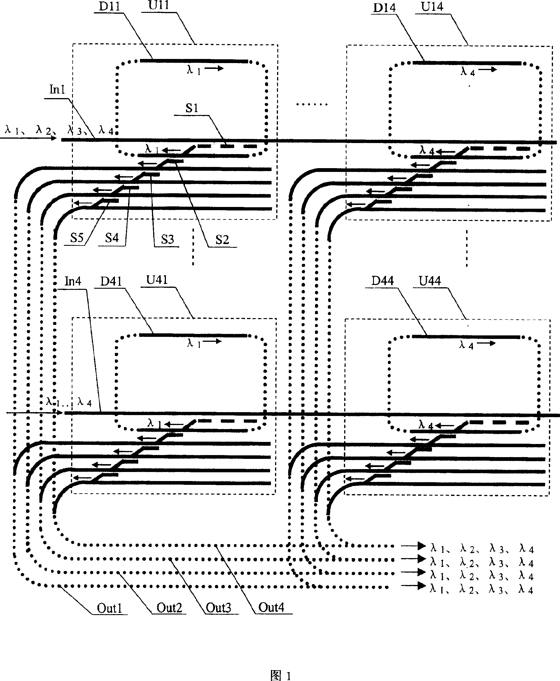
[0028] In Fig. 1, In1 to In4 are input optical waveguides, where In2 and In3 are not shown, Out1 to Out4 are the total output optical waveguides of the device, and each input optical waveguide of In1 to In4 has λ1, λ2, λ3 and λ4 four optical channels of different wavelengths. U11 is a 1×(4+1) optical switch array corresponding to the light wave with a wavelength of λ1 in the first input optical waveguide In1, which is composed of five-stage optical switches S1, S2, S3, S4, and S5. S1 uses an optical switch based on a wavelength selector, which takes out the light wave with a wavelength of λ1 from the first input optical waveguide In1, and the subsequent four stages of U11, namely S2 to S5, use an optical switch based on a directional coupler. The optical switches at all levels in U11 are connected in series, that is, the output optical waveguide of the optical switch Sj with the serial number j is directly connected to the input optical waveguide of the optical switch Sj+1 wit...


PUM


Abstract

The optical switch array is composed of multiple 1X(N+L) optical switch arrays, which is corresponding to each optical channel in each input optical waveguide. Optical switches based on array waveguide interferometer or wave selector are adopted in the first stage of switch array. The said optical switch is capable of separating a light wave in a certain wavelength from input waveguide singly without effecting on other light wave in another wavelength, and sends the separated light wave to any one piece of waveguide among N pieces of output waveguides or L pieces of buffered waveguides stage by stage. Buffered waveguides are in loop type. Output optical waveguides with identical serial number in 1X(N+L) optical switch arrays are connected to output port with serial number in devices. The invention realizes whole optical routes features optical buffering and optical gain, high integrity and available for mass manufacturing.

Description

technical field [0001] The invention relates to the field of integrated optics, in particular to a wavelength-selective optical switch array suitable for all-optical networks, which is suitable for optical cross interconnection, optical switching, and optical routing devices in optical communication networks. Background technique [0002] The optical switch is mainly used to turn on and off the optical channel in the optical fiber communication. The optical switch array can realize the direct exchange of light waves between the optical channels, and is the core device to realize the all-optical network. Optical switches can be divided into two categories: mechanical and non-mechanical. Among them, the mechanical optical switch relies on the movement of optical fibers or optical components to change the optical path and realize the opening and closing of the optical path. Common mechanical optical switches include moving optical fibers, moving sleeves, moving collimators, mo...

Claims


Application Information

Patent Timeline
Patent Type & Authority Patents(China)
IPC IPC(8): H04B10/12H04B10/02G02B6/26G02B6/12H04B10/25
Inventor 李志扬
Owner 李志扬
Why Eureka
Try Eureka