Work condition analogue rolling contact fatigue tester
A technology of rolling contact fatigue and working condition simulation, which is applied in the direction of material inspection, wear resistance testing, and mechanical devices, etc., to achieve the effect of rapid fatigue wear test and shorten the fatigue test time
- Summary
- Abstract
- Description
- Claims
- Application Information
AI Technical Summary
Problems solved by technology
Method used
Image
Examples
Embodiment 1
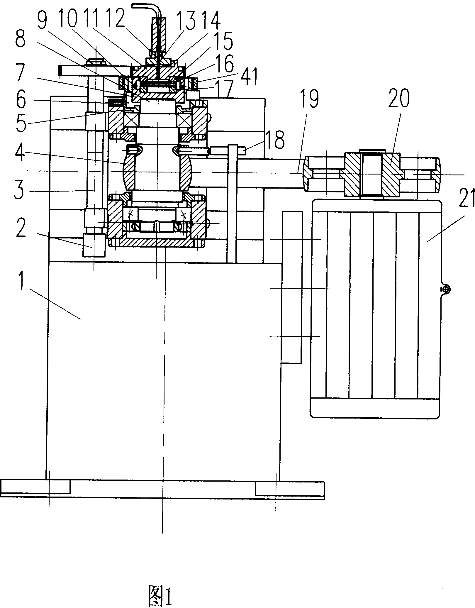
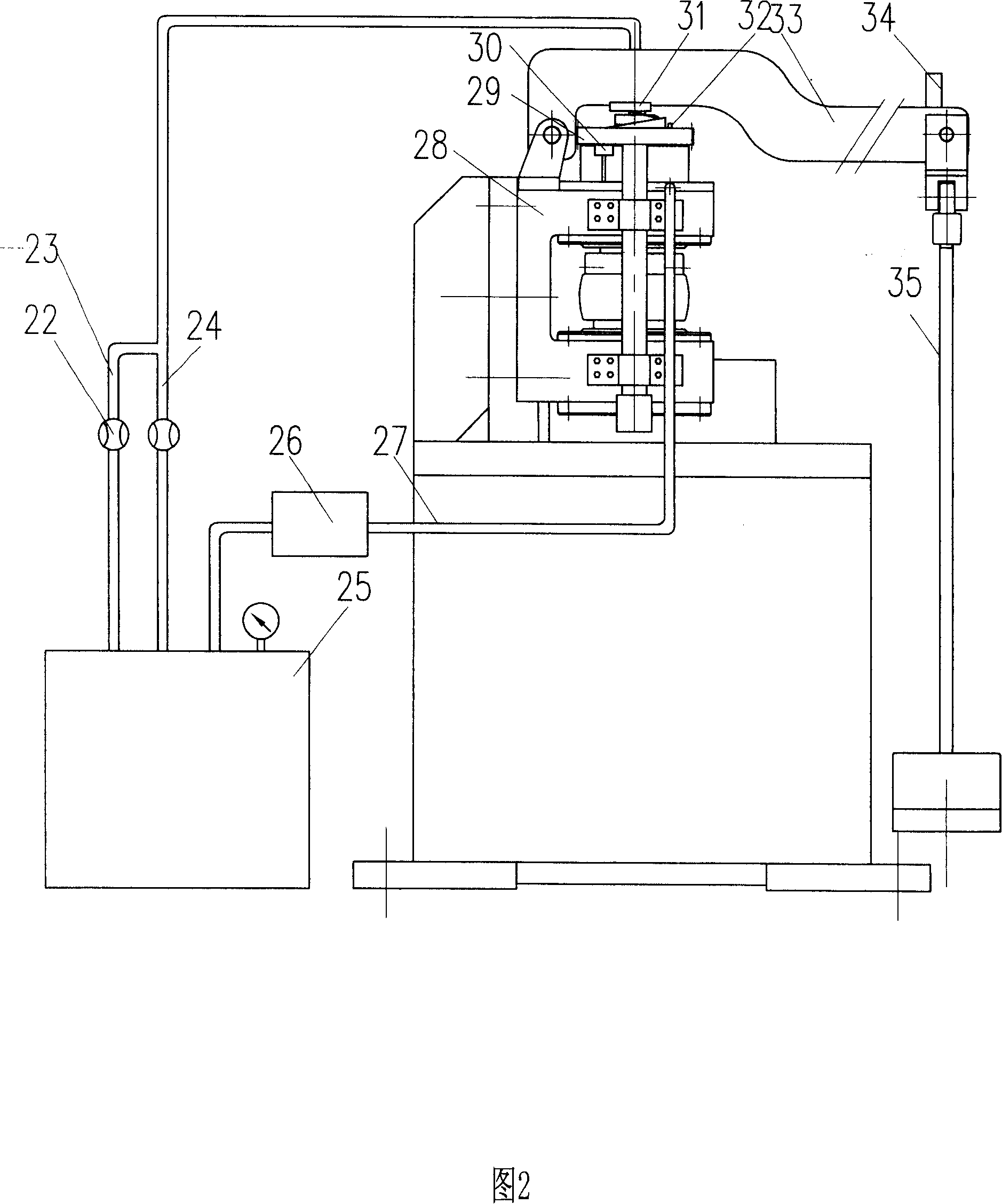
[0027] Fig. 1, Fig. 2 are an embodiment (seeing Fig. 1, Fig. 2) disclosed by the present invention, before the experiment, the surface processing of the upper test piece 15 and the lower test piece 17 that needs to detect is raceway or plane by test requirement , and then the coating material is deposited on the surface of the upper test piece 15, the rolling element 16 or the lower test piece 17 with the coating process equipment. Put the test piece into the test chamber 7, start the motor 21 to adjust the speed, then load, start the lubricating cooling device 25 and the signal acquisition device. The large pulley 20 of the variable frequency motor 21 drives the small pulley 4 and the transmission shaft 8 to rotate through the belt 19, and transmits the speed signal to the speed sensor 18, the transmission shaft 8 drives the test chamber 7 to rotate together, and the rolling body 16 and the lower test piece 17 follow of rotation. According to the test requirements, the lubri...
Embodiment 2
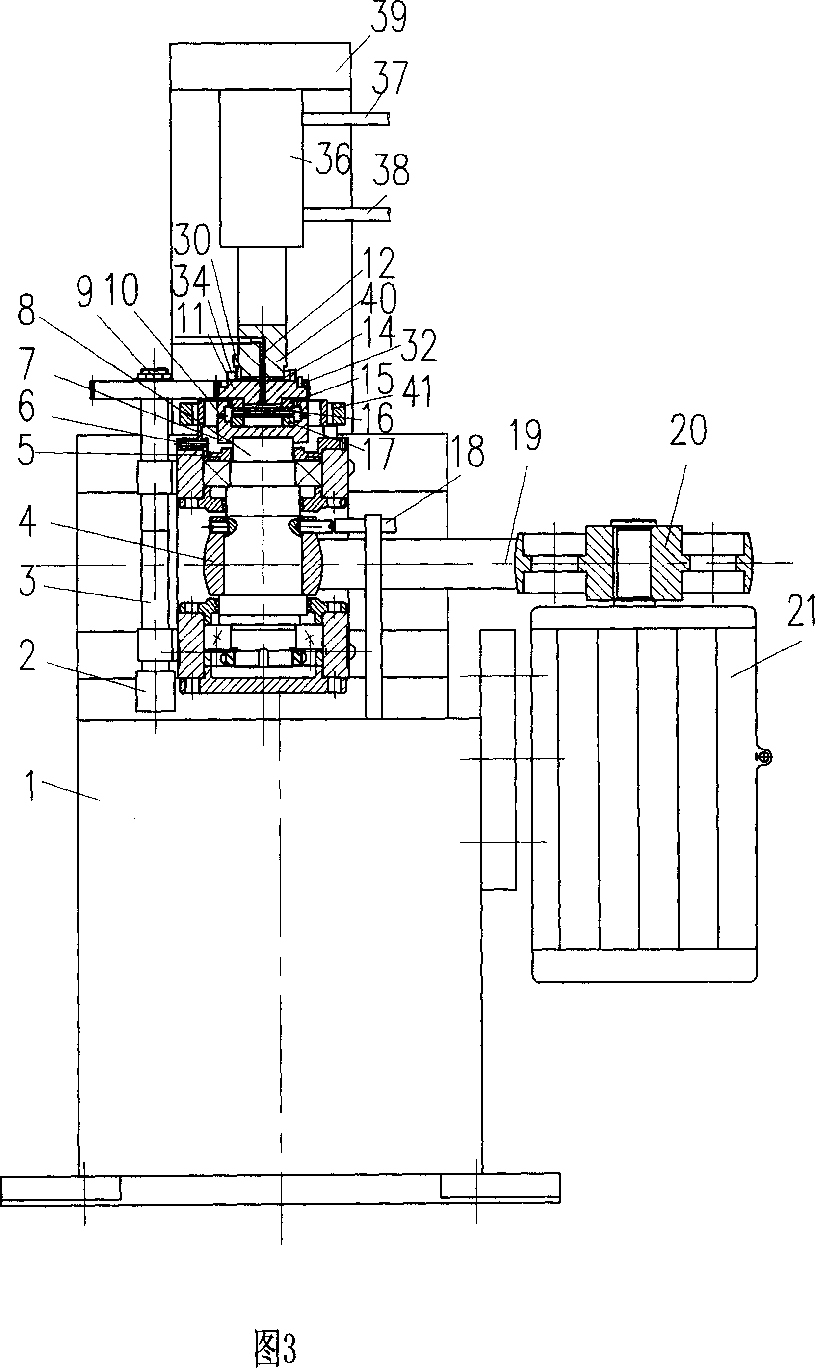
[0029] Fig. 3 is another embodiment disclosed by the present invention (see Fig. 3), and the upper end of hydraulic cylinder 36 is fixedly connected with frame 39, and hydraulic pressure block 40 is installed on the piston rod of hydraulic cylinder 36, and acceleration sensor 34 is threadedly connected to emergency Stop on the cam 11 arc plane. Temperature sensor 32 is placed in the groove of emergency stop cam 11, and cylinder cam contacts with contact switch 31. The frequency conversion motor 21 drives the large pulley 20 to drive the small pulley 4 through the belt 19, the small pulley 4 drives the transmission shaft 8 to rotate, the transmission shaft 8 is fixed on the bracket 28 through the bearing and the bearing support, and the upper end of the transmission shaft 8 is connected to the test chamber 7 to drive the lower test piece 17 rotates, the upper end of the upper test piece 15 is the emergency stop cam 11, the teeth of the emergency stop cam 11 mesh with the gear 2...
PUM
 Abstract
Description
Claims
Application Information
 - R&D
- Intellectual Property
- Life Sciences
- Materials
- Tech Scout
- Unparalleled Data Quality
- Higher Quality Content
- 60% Fewer Hallucinations
Browse by: Latest US Patents, China's latest patents, Technical Efficacy Thesaurus, Application Domain, Technology Topic, Popular Technical Reports.
© 2025 PatSnap. All rights reserved.Legal|Privacy policy|Modern Slavery Act Transparency Statement|Sitemap|About US| Contact US: help@patsnap.com


