Eureka AIR delivers breakthrough ideas for toughest innovation challenges, trusted by R&D personnel around the world.

Method for collecting solar energy and its heating apparatus

A heating device and solar energy technology, which is applied in solar thermal devices, solar thermal power generation, heating devices, etc., can solve problems such as inconvenient maintenance, difficult installation and construction, and large changes in ambient temperature, so as to reduce manufacturing costs and difficulty in construction , Improve operational reliability, low heat recovery and high heating efficiency

Inactive Publication Date: 2008-06-04
无锡中节能建筑能源有限公司
View PDF4 Cites 0 Cited by
  • Summary
  • Abstract
  • Description
  • Claims
  • Application Information

AI Technical Summary

Problems solved by technology

Therefore, the current heat collection method and heat collection structure have the following problems: 1. The cost of manufacturing and using heat collection elements is high
Although the all-glass vacuum tube has the highest thermal efficiency, it has the problems of being fragile and unable to bear pressure; although the metal heat pipe solves the pressure bearing problem, it also increases the complexity of the metal heat pipe manufacturing process, especially the sealing at the port is not easy to solve, resulting in The vacuum degree of the vacuum layer is not easy to guarantee, the heat radiation loss is large, and the thermal efficiency is relatively reduced; although the vacuum plate collector can also solve the pressure problem, the processing technology of the glass vacuum plate is more complicated, and the vacuum degree is lower than that of the metal heat pipe. Low, large heat radiation loss, poor thermal insulation performance, and the lowest heat collection efficiency
At present, in order to reduce the loss of heat radiation, the heat collecting unit has taken measures in terms of heat preservation, but these measures will further increase the manufacturing cost of the heat collecting element
Furthermore, since the liquid flowing through the heat collecting element is circulated in a closed pipeline, and the liquid absorbs heat and expands, a certain pressure will be generated in the pipe, so the heat collecting element requires high manufacturing precision of the liquid pipe. This will not only increase the manufacturing cost of the heat collecting element, but also reduce the working reliability of the heat collecting unit and the whole heating system due to the pressure on the inner tube of the heat collecting element during operation
2. The heating area is small
Based on the structure of the traditional vacuum heat collection unit, the heat collection unit must be placed on a specific tool rack and fixed on the roof. Not only can it not implement large-scale heat collection and use of solar energy, but also the use of special brackets brings difficulties to installation and construction. , but also cause inconvenience to daily maintenance work
3. The reliability of the system is not high
Both solar vacuum tubes and solar vacuum panels are made of vacuum glass, so the glass is extremely vulnerable to damage during large temperature differences or during transportation and installation, which will damage the insulation layer of the heat collecting element, resulting in a decline in heat collection efficiency. Therefore, the working reliability of the solar heating system is not high
4. All-weather heating cannot be realized
However, since the working medium directly absorbs heat energy through the heat-collecting unit, not only the heat-collecting unit cannot be laid in a large area, and the building integration is difficult to solve, but also because the ambient temperature changes greatly every day, the economic performance is not high, and it cannot be widely used.

Method used


Image

  • Method for collecting solar energy and its heating apparatus
  • Method for collecting solar energy and its heating apparatus
  • Method for collecting solar energy and its heating apparatus

Examples


Embodiment Construction

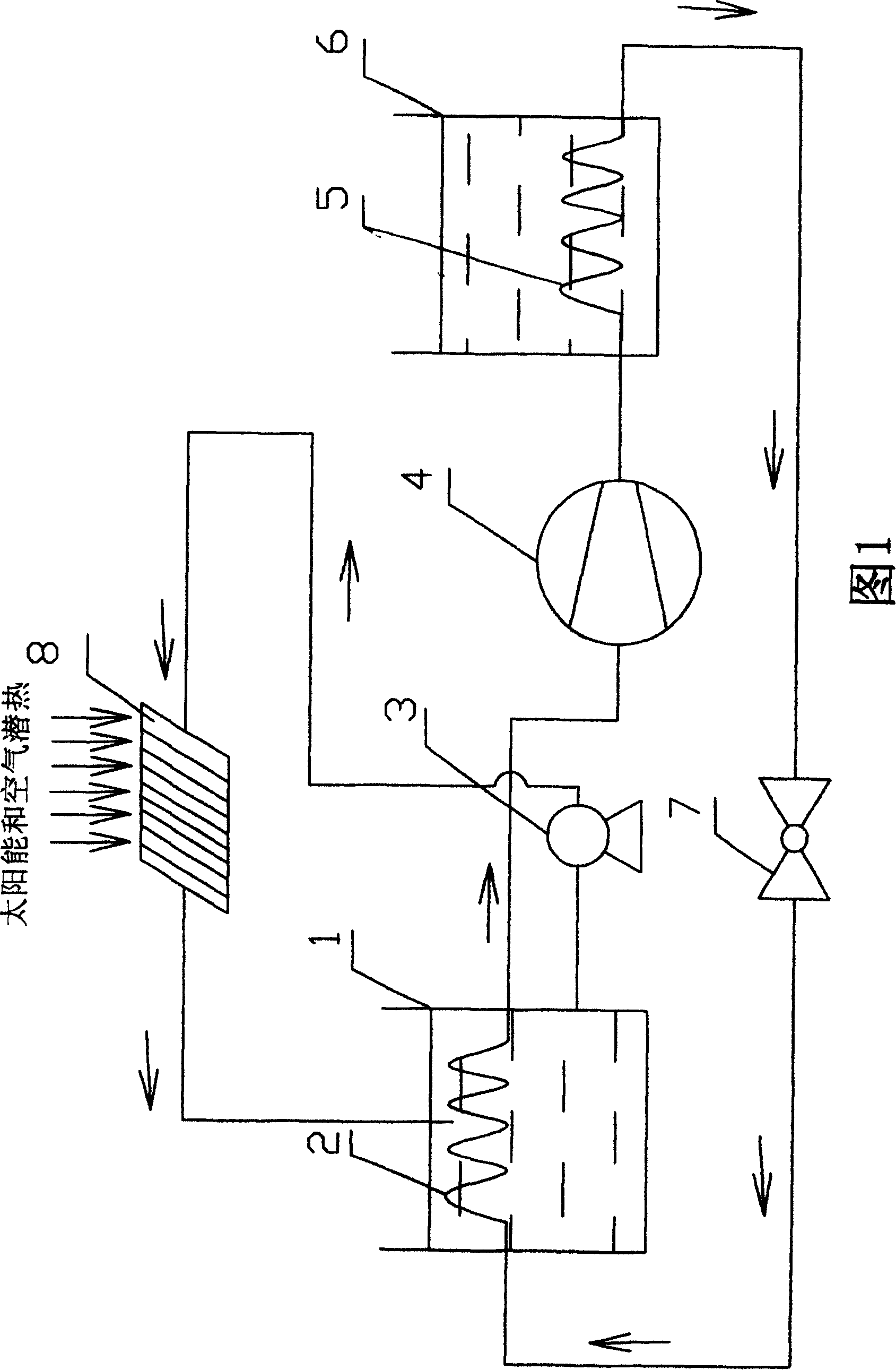
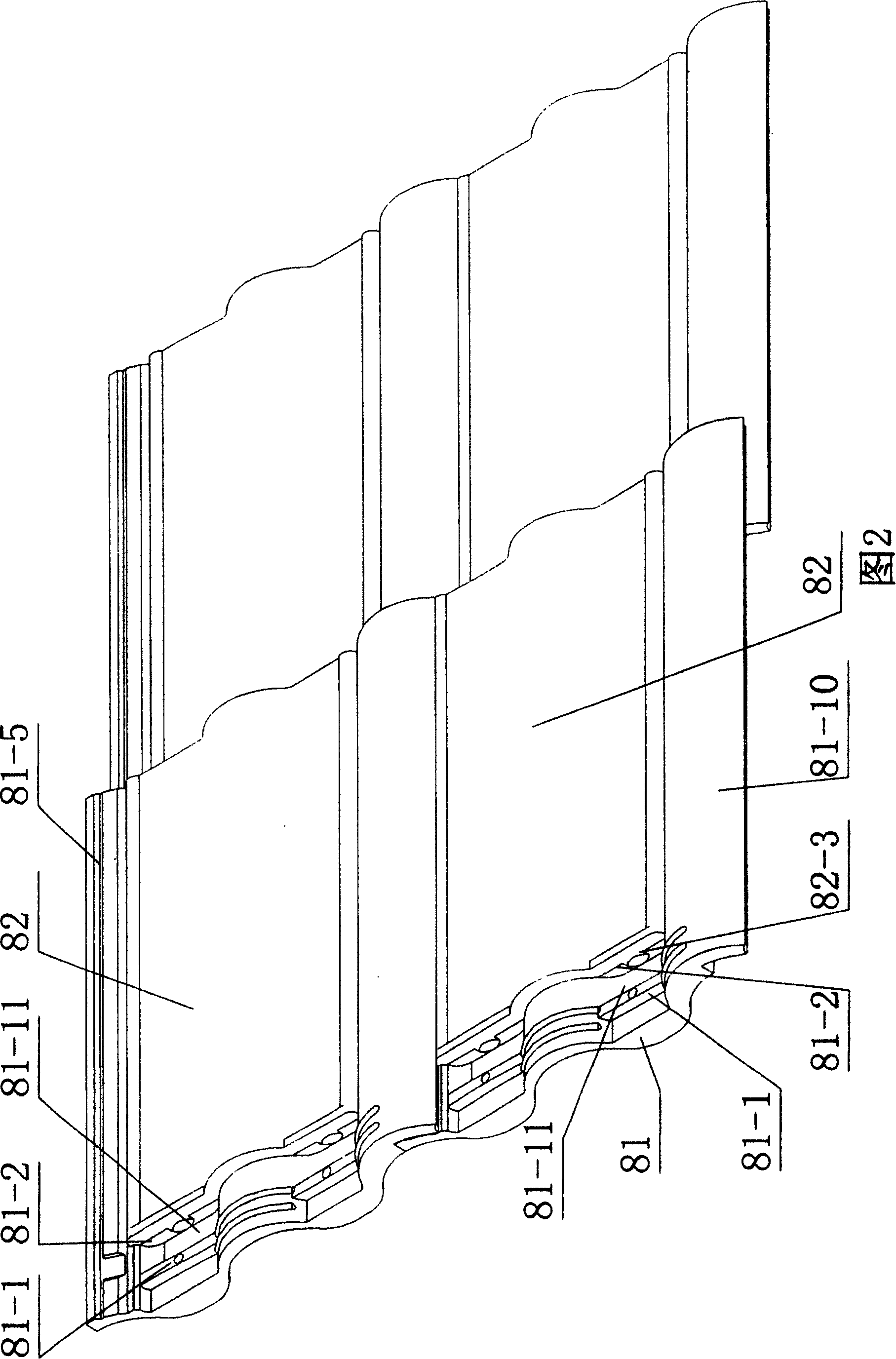
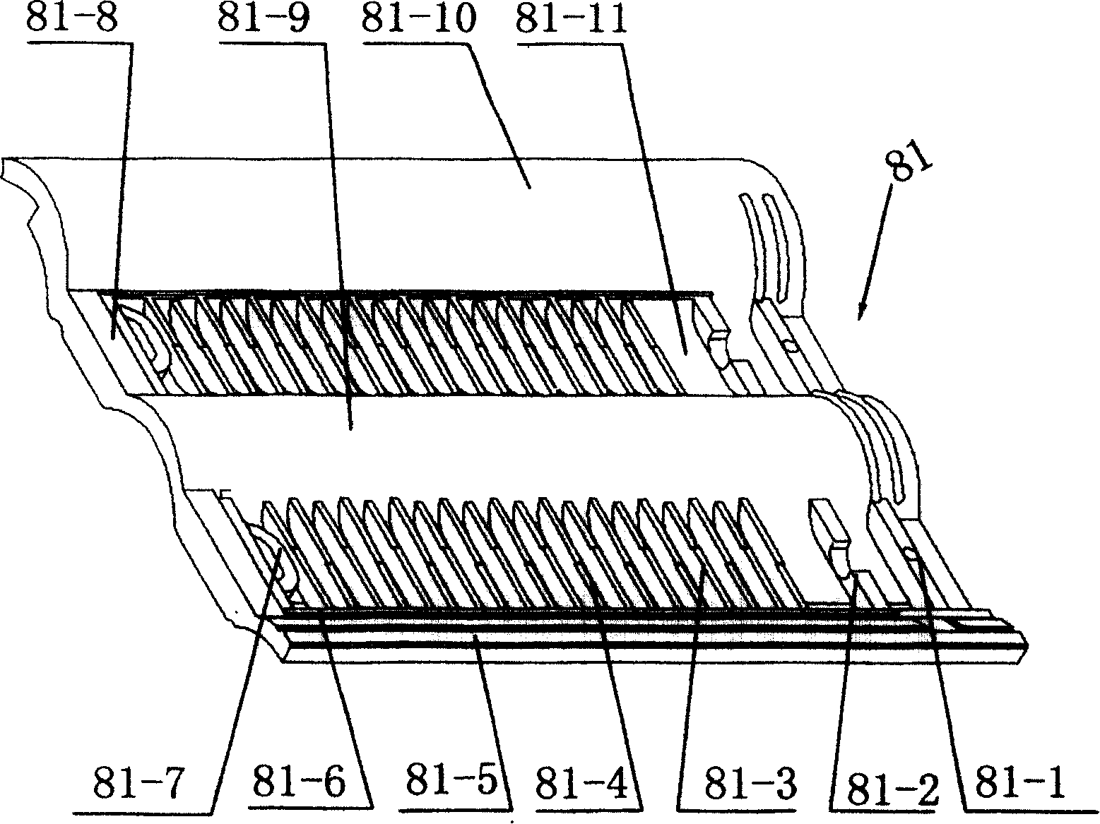
[0023] The method for collecting solar energy of the present invention is to lay a plurality of roof tiles 8 adjacent to each other vertically and horizontally on the inclined roof. The roof tiles 8 have a built-in atmospheric bypass flow channel. There are multiple groups of parallel liquid channels that are open vertically to the atmosphere. The liquid flowing from top to bottom in the liquid channels of the roof tile 8 absorbs solar heat or / and air heat through the tile body, and the liquid adsorbed in the liquid channel adsorption layer absorbs heat. After desorption, one-way heat transfer is formed, and the liquid absorbs heat as a low-temperature heat source.

[0024]See the solar heating device of the present invention shown in Fig. 1, comprise roof tile 8, the evaporator 2 that is arranged in the heat storage tank 1 of heat medium, the compressor 4 and the condenser 5 that are arranged in the storage tank 6 and expansion valve 7. The pipeline connects the evaporator 2,...


PUM


Abstract

The invention relates to a method for collecting solar energy and its heating device, the tile laid on the slant roof lengthwise or transversely has internal constant pressure flow channels, each liquid channel of the tile is opened from up down and is connected to air, it forms single direction heat transmission when the liquid flowing from up down and absorbs solar energy through the tile, the liquid can be used as low temperature heat source. The invention uses roof tiles as heat collecting units, it not only can be laid on the roof with a large area and integrated with the building, it realizes low temperature heat collecting function, and forms single direction transmission for heat energy. It decreases the cost for collecting solar heat energy greatly.

Description

technical field [0001] The invention relates to a solar heat utilization technology, in particular to a method for collecting solar energy and a heating device thereof. Background technique [0002] As an economical and pollution-free energy source, solar energy has been widely used in industry and people's life. However, due to the extremely low energy flux density of solar energy, the main equipment for collecting solar energy, the heat collecting element, has become one of the key technologies for solar energy utilization. After years of improvement, the current typical heat-collecting elements use vacuum tubes or vacuum panels to absorb solar energy. The liquid in the vacuum tubes / plates absorbs direct sunlight and scattering of solar radiation, and accumulates and stores high-temperature heat energy for circulation. However, heat absorption by the vacuum tube / plate is two-way transmission, so the temperature difference between the high temperature of the liquid after t...

Claims


Application Information

Patent Timeline
Patent Type & Authority Patents(China)
IPC IPC(8): F24J2/04E04D13/18F25B30/06F24H4/04F24J2/00
CPCY02E10/44Y02B10/20
Inventor 杨家华王伟强唐晓东杨斌旭张利平何安江
Owner 无锡中节能建筑能源有限公司
Why Eureka
Eureka Blog
Learn More