
Cutting head for machine tool

A technology of mechanical tools and cutting heads, which is applied in the field of light cutting heads, can solve the problems of no description, increase drill pipe, reduce vibration, etc., and achieve the effect of long cantilever length, increasing natural frequency and increasing natural frequency

Inactive Publication Date: 2008-07-02
TEENESS AS
View PDF7 Cites 0 Cited by
  • Summary
  • Abstract
  • Description
  • Claims
  • Application Information

AI Technical Summary

Problems solved by technology

The patent describes a complex system based on circuits that reduce drill pipe vibration
[0004] EP-0 342 692 shows a cutting tool, but does not describe how to reduce vibration or how to lengthen the drill rod

Method used


Image

  • Cutting head for machine tool
  • Cutting head for machine tool

Examples


Embodiment Construction

[0026] The invention is further described by the following examples.

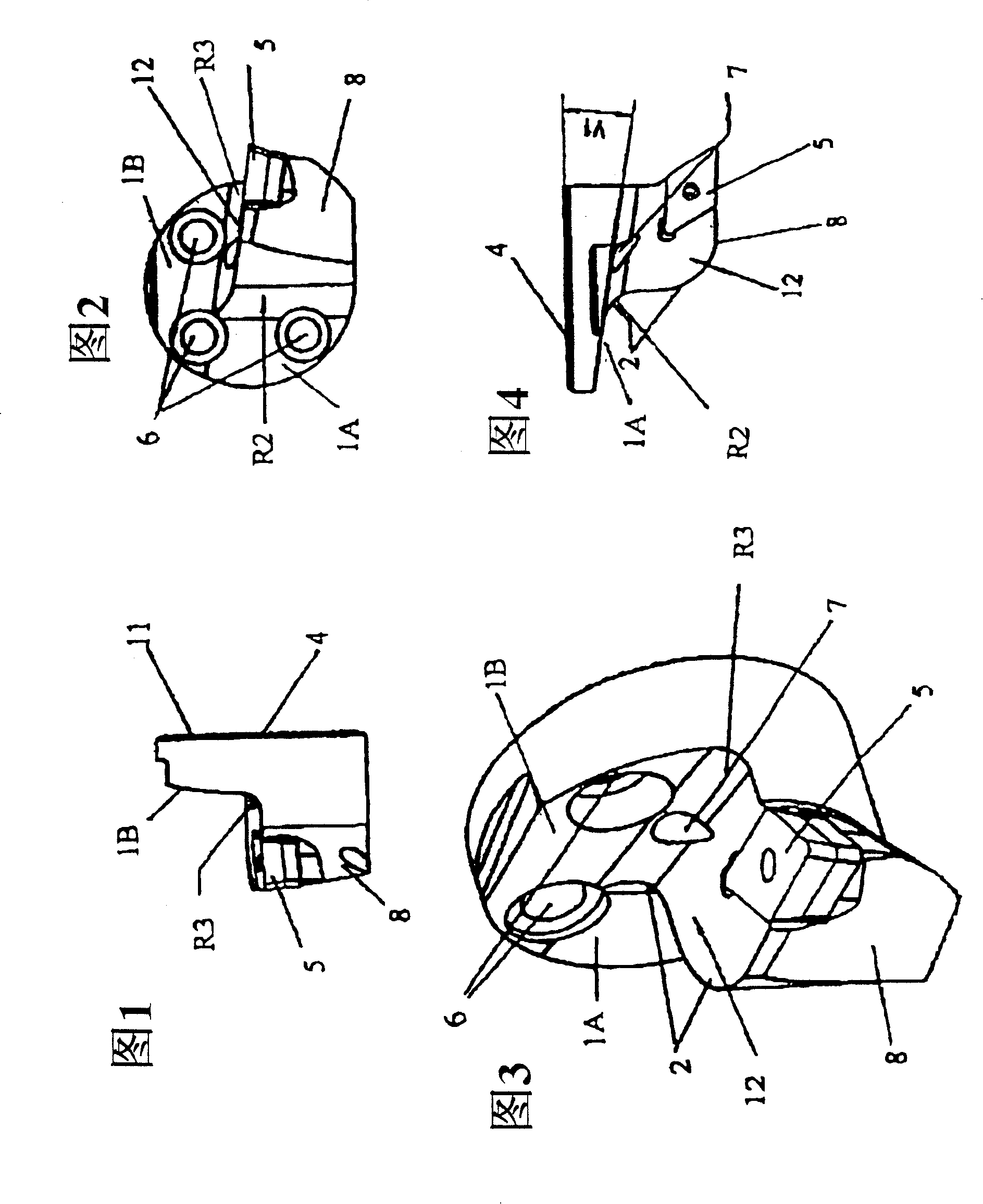
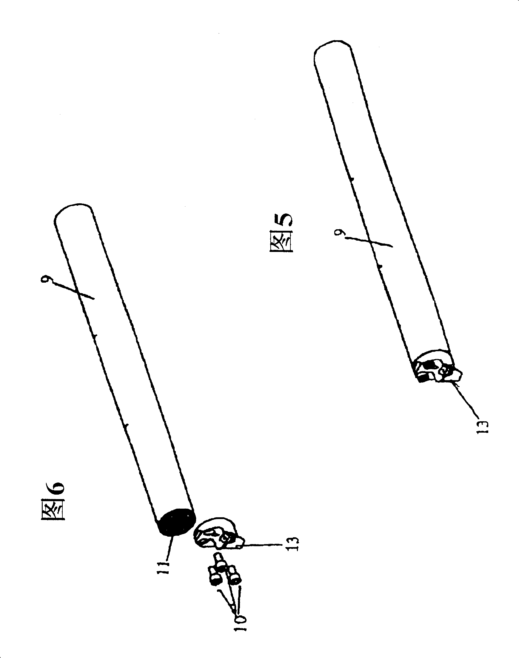
[0027] The side view of the cutting head shown in Figure 1 has a joint surface 4 on which there are serrations 11 and a protrusion 8 with an upper surface or slope 12, and the cutting head further comprises a cutting blade 5 and a cutting blade. The fixed surface of the blade. Also shown, with respect to the joint surface, is a free slope 1B that transitions on the protruding portion 8 towards the slope 12 into a concave surface R3. The protruding portion 8 comprises an element (not shown) for fixing the cutting insert 5 . Methods of securing cutting inserts are known in the art and so will not be further described here.

[0028] Figure 2 shows a front view of the adapter shown in Figure 1 showing holes for securing the cutting head to the adapter with threads and bolts. Also shown are the cutting inserts 5 on A1 , 1B and on the protruding portion 8 .

[0029] Figure 3 shows the transition from the flan...


PUM


Abstract

The invention concerns a cutting head (13) to be secured in an adapter (9) in a machine tool for chip removing machining. The cutting head (13) comprises a flange with a first side creating a coupling surface (4) adapted for being secured to the adapter (9). On the opposite of the flange, it is situated an other side creating at least one surface (1A) with an outwards extending protrusion (8), with securing means adapted for securing a cutting insert (5) with at least one cutting edge. The weight of the cutting head (13) is reduced as compared to the strength of the cutting head (13), and the natural frequency of the cutting head (13) is thereby increased when this is secured to the adapter (9).

Description

technical field [0001] The present invention relates to cutting heads of the type used in drill rods and similar tool holders in machine tools. They are used in-house in the turning process. In particular, the present invention relates to a special light duty cutting head which provides a higher natural frequency adapter which allows the adapter to be longer than currently commonly used adapters. Background technique [0002] When internal turning is performed, since the lowest natural frequency and the natural vibration generated by the shear force or cutting force in the cutting process area are in the same area, vibration and blockage are prone to occur. This results in poor quality of the machined surface, noise and poor accuracy of the workpiece. Some vibration-damping techniques have been developed to allow machining with tools up to 14 times the diameter of the drill pipe. [0003] An example of a vibration damping system for use in drill pipe is shown in US Patent...

Claims


Application Information

Patent Timeline
Patent Type & Authority Patents(China)
IPC IPC(8): B23B29/04B23B27/00B23B29/03B23B27/10B23B29/12
CPCB23B27/007B23B29/046Y10T407/14Y10T407/227Y10T82/2585
Inventor 特露德·霍尔佩尔·比约维克波尔·索利克努特S·斯托克兰德
Owner TEENESS AS
Learn More