
Positioning precision detecting method and device for medical radiotherapy equipment

A radiation therapy and positioning accuracy technology, which is applied in the detection of positioning accuracy of medical radiation therapy-related equipment and its devices, can solve the problems of error-prone, manual detection procedures, and long time, and achieve the effect of low-cost detection

Inactive Publication Date: 2008-07-23
杨诚 +1
View PDF3 Cites 1 Cited by
  • Summary
  • Abstract
  • Description
  • Claims
  • Application Information

AI Technical Summary

Problems solved by technology

[0005] 1. There are many manual inspection procedures, long time, error-prone, and high experience requirements for operators;
[0006] 2. It can only be tested qualitatively, but not quantitatively, and cannot digitally display the detected errors, resulting in different understandings of errors by everyone;
[0007] 3. It cannot detect in real time, and cannot dynamically track and record the motion accuracy of the tested equipment;
[0008] 4. Errors cannot be comprehensively analyzed. Errors are often caused by the interconnection of the entire system, which is very intricate, and operators cannot perform large-scale comprehensive system error analysis and simulation operations;
[0009] 5. In the detection environment with rays, personnel cannot approach the detection and observe the detection content in real time

Method used


Image

  • Positioning precision detecting method and device for medical radiotherapy equipment
  • Positioning precision detecting method and device for medical radiotherapy equipment
  • Positioning precision detecting method and device for medical radiotherapy equipment

Examples


Embodiment 1

[0079] Example 1: Verification of the three-dimensional coordinate system of the laser positioning lamp

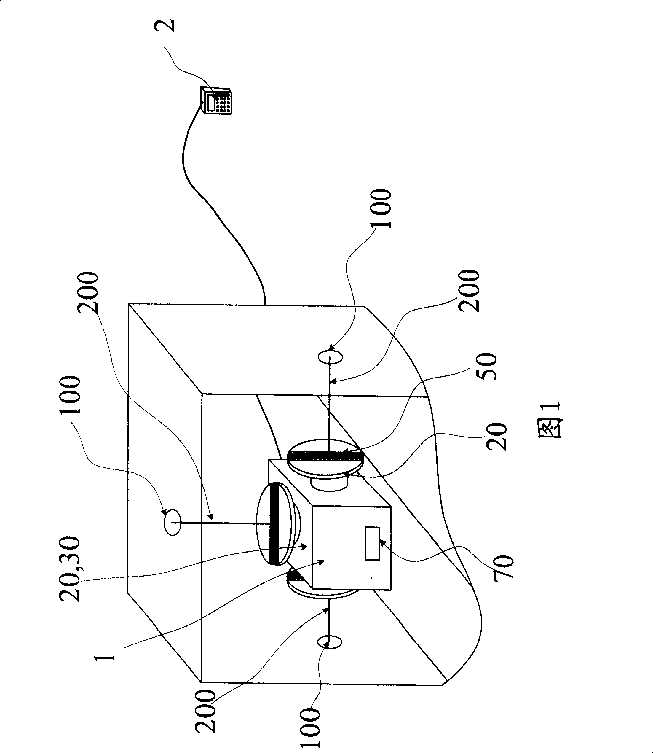
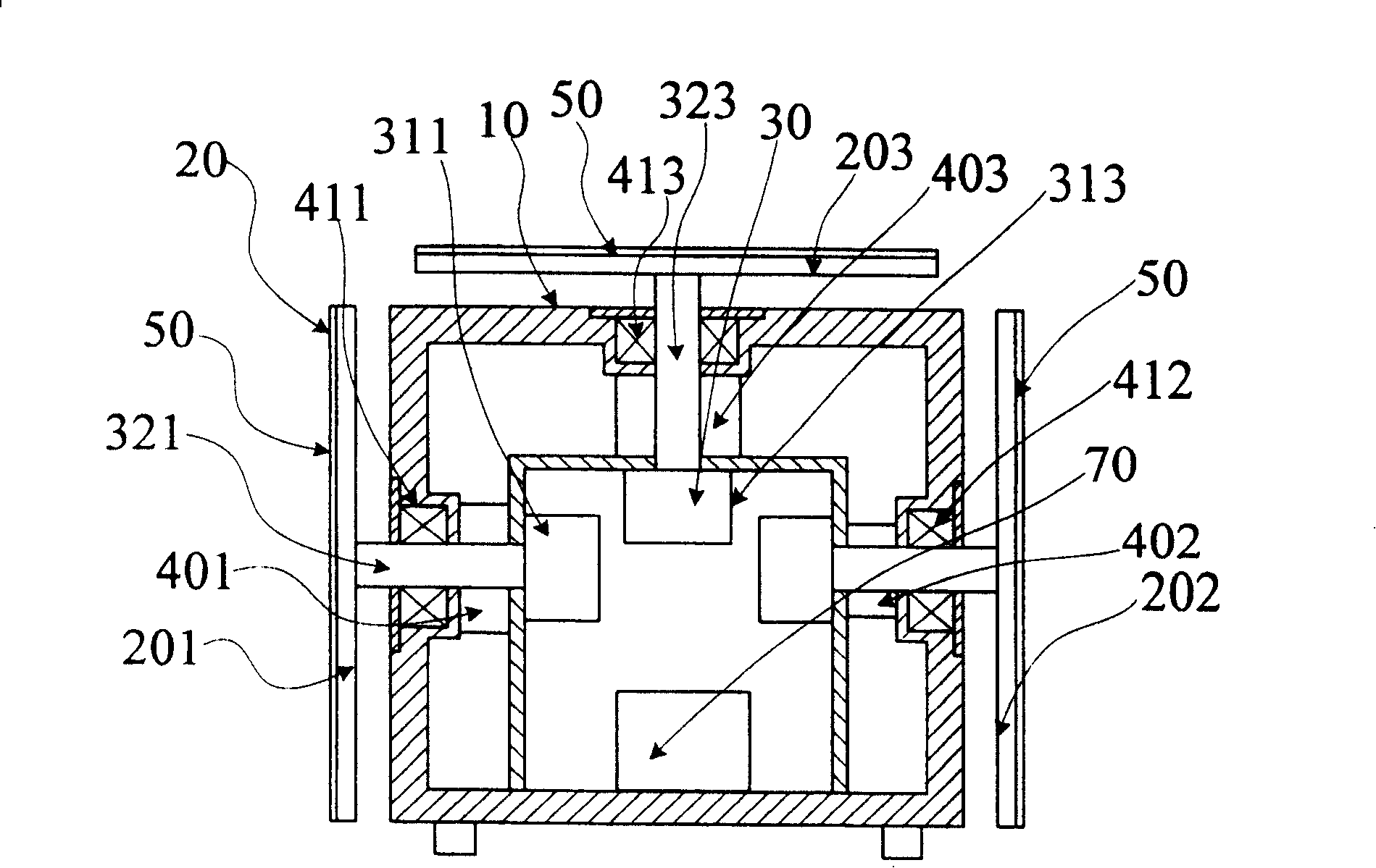
[0080] First, place the sampling host 1 on the accelerator treatment bed, and use the inclination sensor 70 on the sampling host 1 to check the horizontality of the X-axis and Y-axis on the treatment bed (if the bed is not level, you can pass the adjustment mechanism to level). Confirm that the bed surface has risen to the height where the left turntable 201 and right turntable 202 of the sampling host 1 can receive the laser positioning crosshairs on the left and right sides, and start the detection function. At this time, the left turntable 201 and right turntable 202 of the sampling host 1 start to rotate at a constant speed, and the photosensitive sensors on the two turntables convert the optical signals of the laser positioning lights on the left and right sides into electrical signals, which are converted by A / D and passed through the serial port. Send to Handset 2....

Embodiment 2

[0081] Example 2: Verifying the size of the accelerator light field

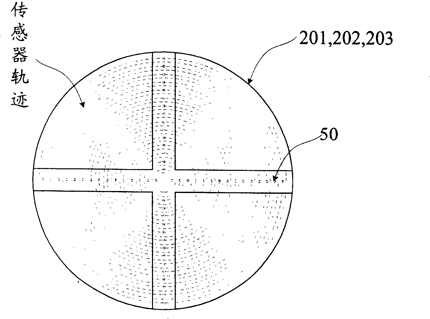
[0082] After verifying the three-dimensional coordinate system of the laser positioning lamp in "Example 1", it is ensured that the entire coordinate system is not out of tolerance compared with the theoretical coordinate system in the above figure (if it is out of tolerance, first correct it, and then in Example 2 detection), in this way, it can be ensured that the central beam axis of the accelerator is perpendicular to the upper surface of the top turntable 203 of the sampling host 1. Turn on the accelerator field light, open and close the beam collimator to the detection state, the light field shines on the top turntable 203 of the sampling host 1, and click the detection button on the control interface of the handheld controller 2, so that the sampling host 1 The top turntable 203 starts to rotate and detect, and the detected spot profile is as follows: Figure 5 In the black track, the embedded comput...


PUM


Abstract

The present invention relates to method and device for detecting the positioning precision of medical radiotherapy equipment. The device includes one sampling unit for acquiring the position information of the irradiation points of the medical radiotherapy equipment, and one hand held controller for processing the acquired sampling information and sending sampling request command to the sampling unit. The sampling unit includes one casing, three turntables on the casing with one-dimensional sensor array to receiving the laser positioning information from three positioning laser lamps and the analog lighting information of the medical radiotherapy equipment. The present invention has low detection cost.

Description

technical field [0001] The invention relates to the technical field of using optical means to test or analyze positioning accuracy, in particular to a method and a device for judging the positioning accuracy of important parts of medical equipment by using infrared laser propagation characteristics. The method and device of the invention are particularly suitable for checking the positioning accuracy of equipment related to medical radiotherapy. Background technique [0002] In the field of medical radiation therapy, X-rays and γ-rays produced by medical linear accelerators, Co60 treatment machines, and γ-knife have important therapeutic effects on killing cancer cells and inhibiting the spread of cancerous sites. However, radiation must be confined within the lesion range during treatment. If the positioning error of these devices is too large, the range of radiation exposure will be inaccurate, and the side effects on normal human tissues and dangerous organs will also be ...

Claims


Application Information

Patent Timeline
IPC IPC(8): A61B6/00G12B13/00G01M19/00G01M99/00
Inventor 洪红光牛道立杨诚李强杨冠军
Owner 杨诚
Learn More