New type optical cable

A new type of optical cable technology, applied in the field of new optical cables, can solve problems affecting the information transmission performance of optical cables, uneven force, large internal stress of optical cables, etc., to ensure information transmission performance, reduce uneven force, and reduce construction difficulty Effect

Inactive Publication Date: 2008-08-20
HANGZHOU FUTONG COMM TECH CO LTD
View PDF14 Cites 0 Cited by
  • Summary
  • Abstract
  • Description
  • Claims
  • Application Information

AI Technical Summary

Problems solved by technology

Even so, there are still many defects in this structure: first, the optical fiber ribbon of the ribbon optical cable is composed of several optical fibers juxtaposed. The optical fiber is subjected to a large external force (twist and extrusion) to affect its transmission performance, and the greater the information transmission capacity, the more optical fibers need to be arranged in parallel, and the greater the width of the optical cable, in its width direction The more uneven the stress on different parts of the cable, the more difficult it is for the stress buffer structure to share the external force on the optical fiber in the middle of the cable, and the easier it is to twist
Secondly, the copper conductor or Kevlar element used as a strengthening element cannot bear a large external force, especially in the case of outdoor overhead, the effect on the optical cable caused by wind, ice and other climatic factors in the external environment is copper Conductor or Kevlar (Kevlar) components can not withstand, and there must be a large external force applied to the optical fiber to affect the information transmission performance of the optical fiber, so it is only suitable for occasions without large external force
Third, during use, changes in environmental factors, such as the temperature difference between day and night, will cause the optical fibers with different thermal expansion coefficients, the stress buffer structure, and the protective layer that encapsulates the two to expand by different orders of magnitude, causing the optical cable itself to swell. Large internal stress affects the information transmission performance of the optical cable; moreover, in the manufacturing process, especially in the process of encapsulating the optical fiber and the strengthening element with the protective layer, thermal stress will also be generated, and it is often greater than the external environment The influence of thermal expansion caused by the change of factors, which is also insurmountable by the ribbon cable itself
Fourth, this kind of ribbon cable composed of multiple optical fibers in parallel has grooves between adjacent optical fibers, but because the diameter of the optical fiber is only about 0.25 mm, it is difficult to peel the optical fiber from the protective layer during connection , which increases the difficulty of construction; at the same time, multiple grooves complicate manufacturing
In addition, in this technical scheme, the material provided for manufacturing the protective layer is polyvinyl chloride, because when polyvinyl chloride burns, smoke will occur, and hydrogen halide poisonous gas will be produced, causing serious consequences, which is also related to the large population density. Indoor (office buildings, etc.) use bury hidden dangers

Method used


Image

  • New type optical cable
  • New type optical cable
  • New type optical cable

Examples


Embodiment 1

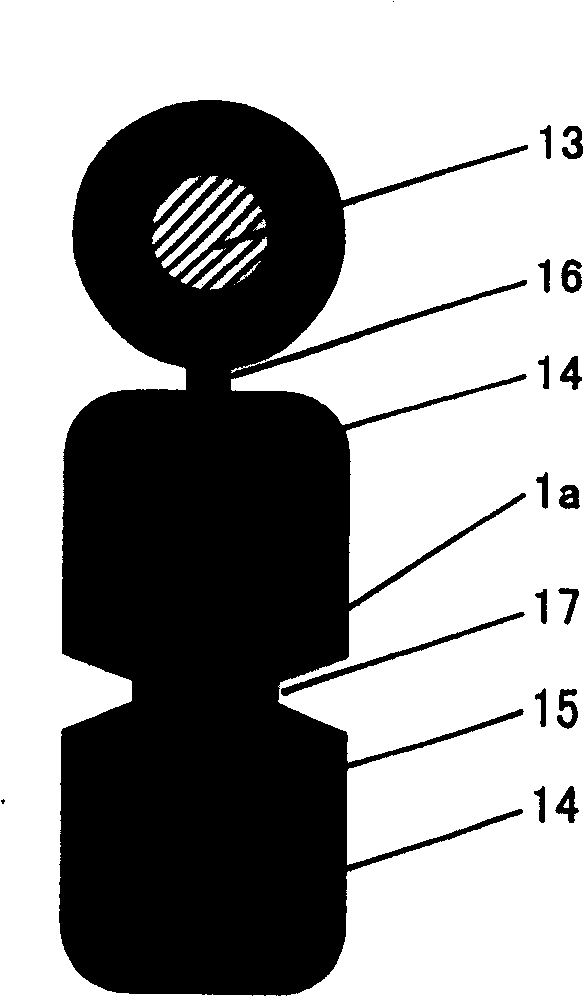
[0020] Embodiment one: figure 1 Shown optical cable, its manufacture step is (see Figure 5 ): the steel wire, the GFRP linear reinforcement and the single optical fiber that are released through the steel wire pay-off device 51, the GFRP pay-off device 53, and the fiber pay-off device 54 respectively pass through the extrusion mold of the assembly line device 55 and the extruder 56 (see Image 6 ), cooling water tank 57, traction pulley 58, and finally coiled by tension control wire receiving and arranging device 59 (wherein steel wire also passes through decontamination straightening device 52); meanwhile, steel wire, two GFRP reinforcements, and optical fiber first pass through the inner Four positioning holes 61, 62, 63, 64 on the mold 6, and then make the steel wire pass through the round hole 71 on the outer mold 7, two GFRP reinforcements and optical fibers through the waist-shaped hole 73 on the outer mold together, And make the optical fiber correspond to the "V"-sh...

Embodiment 2

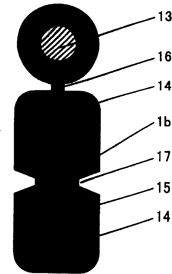
[0023] Embodiment 2: According to the manufacturing steps of Embodiment 1, the information transmission medium is changed from one optical fiber to two optical fibers 1b, and two pay-off racks are used for optical fiber pay-off, which can be obtained as follows figure 2 The cable shown has a maximum outer dimension of 4.0mm x 2.0mm. After performance testing, the attenuation constant of the optical cable is: 1310nm window 0.32 ~ 0.40dB / km, 1550nm window 0.18 ~ 0.25dB / km, and under the test conditions of 660 Newton tension and 1000 Newton / 100mm flattening force Attenuation change is less than 0.03dB / km.

Embodiment 3

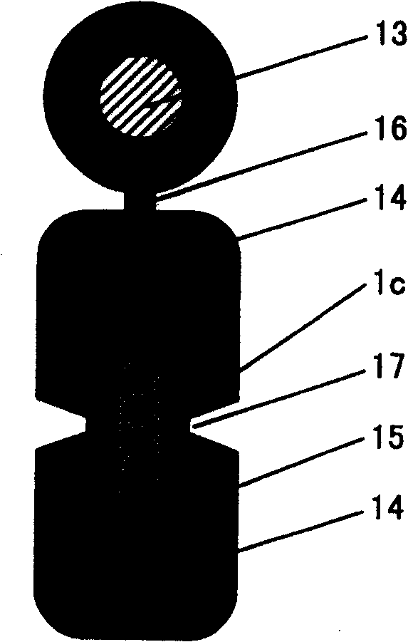
[0024] Embodiment three: according to the step of embodiment one, change the information transmission medium into a four-core optical fiber bundle 1c (this optical fiber bundle is a bundle-shaped object with a rectangular cross section), and the optical fiber bundle pay-off adopts a single optical fiber bundle pay-off stand, The pay-off tension of optical fiber bundle 1c is controlled at about 175 gram force, can make such as image 3 The cable shown has a maximum outer dimension of 6.0mm x 2.0mm. After performance testing, the attenuation constant of the optical cable is: 1310nm window 0.32 ~ 0.40dB / km, 1550nm window 0.18 ~ 0.25dB / km, and under the test conditions of 660 Newton tension and 1000 Newton / 100mm flattening force Attenuation change is less than 0.03dB / km.


PUM


Abstract

The present invention features that information transmission medium, stress bearing part and stress distributing part are extended in the same direction and made to penetrate one through hole in extruding mold while thermoplastic plastic is extruded to form the integral optical cable with protecting casing. The information transmission medium is single fiber or fiber bundle. The optical cable has parallel parts, no cross, homogeneous stress, small inner stress and high information transmission performance.

Description

【Technical field】 [0001] The invention relates to an optical cable with a novel structure and a manufacturing method thereof, in particular to an optical cable which can withstand various external forces and does not affect its performance due to changes in environmental factors, so that it can be used in building complex communities, It can also be used in intelligent office buildings, shopping malls, hotels and residential buildings. 【Background technique】 [0002] With the rapid development of my country's communications industry, the construction of long-distance core network optical cables between provinces and major cities has basically taken shape, and optical cables for local loop networks, user loop networks, and cable television networks have increasingly attracted people's attention. Pay attention to. The common ones usually include central bundle tube type optical cable (such as the utility model patent whose notification number is CN2326969Y), layer twisted opti...

Claims


Application Information

Patent Timeline
Patent Type & Authority Patents(China)
IPC IPC(8): G02B6/44
Inventor 魏国庆
Owner HANGZHOU FUTONG COMM TECH CO LTD
Why Eureka
Try Eureka