Full solid band-gap optical fiber with low limited loss and low bending loss

A low-bending, all-solid technology, used in cladding optical fibers, light guides, optics, etc., can solve the problems of the influence of lossy fiber deformation, poor bending resistance, and high transmission loss, to optimize the splice loss and improve the mechanical reliability of the optical fiber. performance, reducing the effect of limiting loss

Active Publication Date: 2008-10-15
YANGTZE OPTICAL FIBRE & CABLE CO LTD
View PDF3 Cites 1 Cited by
  • Summary
  • Abstract
  • Description
  • Claims
  • Application Information

AI Technical Summary

Problems solved by technology

[0003] However, at present, for this type of optical fiber, even if the high-order bandgap with relatively low loss is used to guide light, its transmission loss is much higher than that of conventional solid optical fibers, as shown in the literature [G.Bouwmans et al.Opt.Express 13(2005) p.8452] reported a loss of about 20dB / km at 1550nm using the third-order bandgap
In addition, this type of fiber often exhibits poor bending resistance. Even if the high-order bandgap with relatively low confinement loss is used for light guiding, the loss of this type of fiber is easily affected by fiber deformation.

Method used


Image

  • Full solid band-gap optical fiber with low limited loss and low bending loss
  • Full solid band-gap optical fiber with low limited loss and low bending loss
  • Full solid band-gap optical fiber with low limited loss and low bending loss

Examples


Embodiment Construction

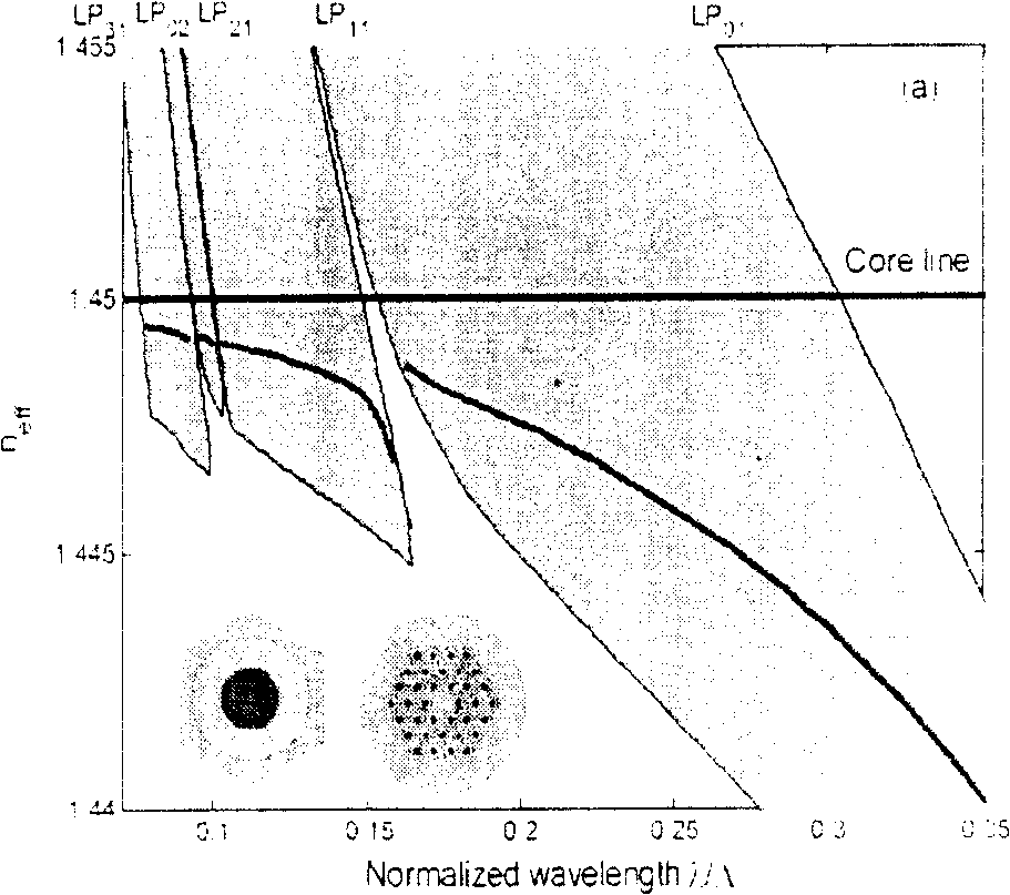
[0022] The working principle of the present invention and various embodiments of this type of optical fiber will be described in detail below with reference to the accompanying drawings. In order to study the light-guiding properties of all solid bandgap fibers, we have adopted the Full-vectorial Plane-wave method (PWM) and the Finite-difference Method (Finite-difference Method) using the ideal matching layer absorption boundary (PML) respectively. , FDM) [S.Guo et al.Opt.Express 12(2004)p.3341] Calculation of bandgap diagram and guided mode of all solid bandgap fiber.

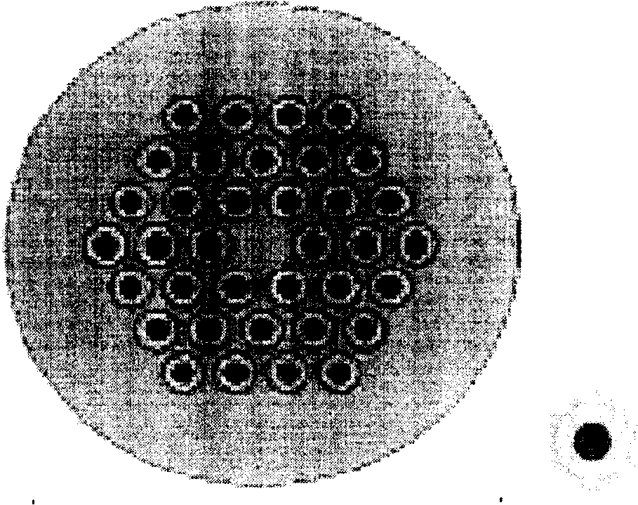
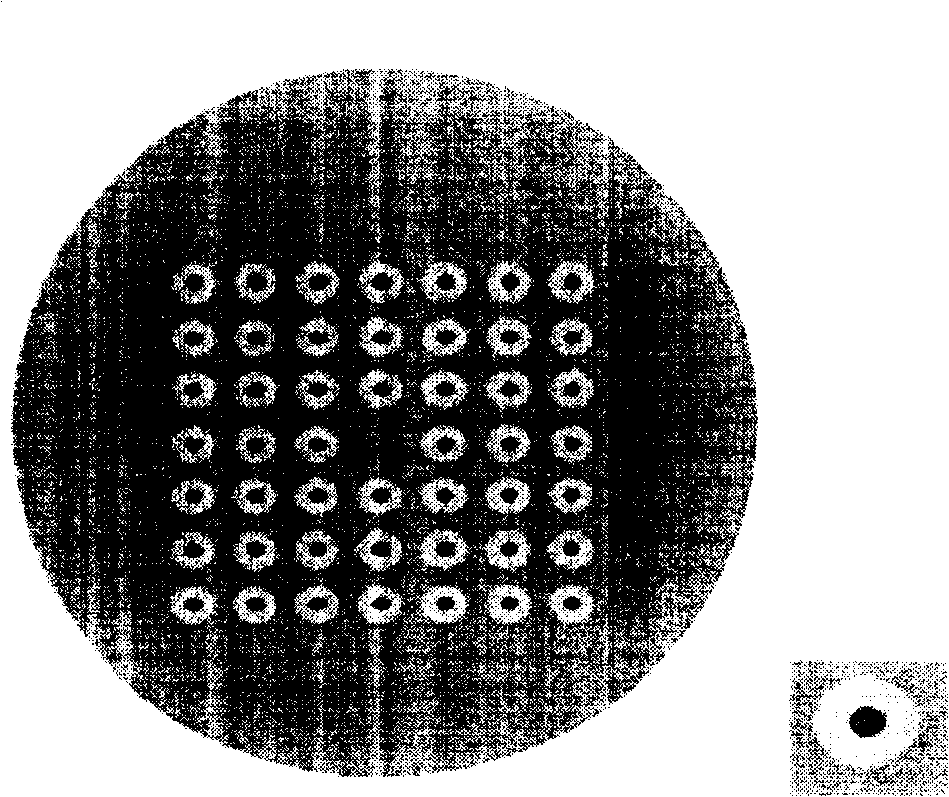
[0023] As embodiment one, the present invention includes a core layer and a cladding layer, and the background material 1 of the optical fiber cladding layer has a certain refractive index n 1 , with a highly doped material with a refractive index n 3 The basic units 3 are distributed on the regular grid nodes of the cladding layer, and at least one layer of low refractive index n is wrapped around the highly...


PUM


Abstract

This invention relates to all solid band gap fibers with a restricted low loss and low bending loss, which includes a core-layer and a cladding layer, the features are: the cladding materials have a refractive index n1, and the basic units with high doped materials with a refractive index n3, which locates on the regular mesh nodes of the cladding layer, and the high doping region of each basic unit are wrapped around with at least one belt region at a low refractive index n2. The invention can be widely applied in the field of photonic optical devices, for instance the fiber amplifier and fiber laser of rare earth doping, and writing for fiber grating etc.

Description

technical field [0001] The invention relates to an all-solid bandgap optical fiber, in particular to an all-solid bandgap optical fiber with low limiting loss and low bending loss, which belongs to the field of optical fiber communication and optical signal processing. Background technique [0002] Photonic Crystal Fiber (Photonic Crystal Fiber), also known as microstructure fiber or holey fiber, is a new type of fiber that has attracted widespread attention in recent years [J.C.Knight, et al.Opt.Lett., 21(1996) p.1547. ; Errata, Opt.Lett.22(1997) p.484], its cross-section has a more complex refractive index distribution, usually the cladding region of this type of fiber contains air holes that run through the entire fiber in different arrangements, these The size of the hole is roughly on the same order of magnitude as the wavelength of the fiber, and the light wave can be confined to propagate in its core region. According to different light guiding mechanisms, photonic c...

Claims


Application Information

Patent Timeline
Patent Type & Authority Patents(China)
IPC IPC(8): G02B6/02
CPCG02B6/02347
Inventor 童维军韩庆荣汪洪海韦会峰
Owner YANGTZE OPTICAL FIBRE & CABLE CO LTD
Why Eureka
Try Eureka