Plasma processing system

A plasma and treatment device technology, applied in the field of plasma treatment devices, can solve problems such as contamination particles, and achieve the effect of suppressing the generation of particles and uniform plasma treatment

Inactive Publication Date: 2008-12-03
SHARP KK
View PDF6 Cites 0 Cited by
  • Summary
  • Abstract
  • Description
  • Claims
  • Application Information

AI Technical Summary

Problems solved by technology

[0009] In a dry etching device with a structure in which electromagnetic waves are introduced through a quartz member, since reaction products adhere to the surface of the quartz member, there is a possibility that particles in the processing chamber may be polluted by the falling reaction products.

Method used


Image

  • Plasma processing system
  • Plasma processing system
  • Plasma processing system

Examples


Embodiment Construction

[0034] Hereinafter, embodiments of the present invention will be described in detail with reference to the drawings. In the following embodiments, an ICP (Ion Coupled Plasma) mode dry etching device is used as an example of a plasma processing device for description. However, the present invention is not limited to the following examples, and is also applicable to dry etching modes other than the ICP mode. Furthermore, the present invention is applicable not only to dry etching apparatuses but also to sputtering apparatuses, CVD (Chemical Vapor Deposition) apparatuses, and the like that perform plasma processing.

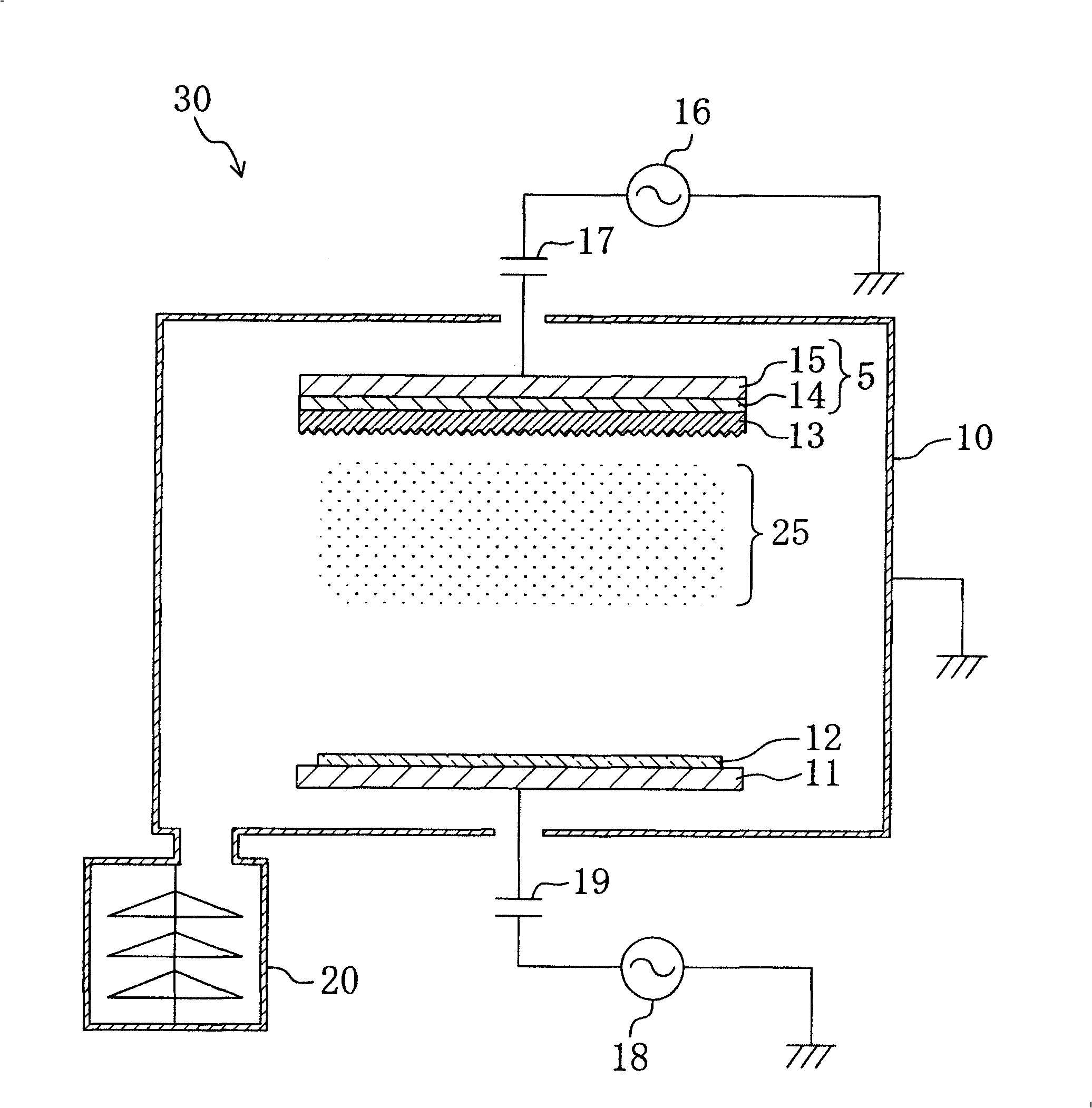
[0035] Below, refer to figure 1 The dry etching apparatus 30 according to the embodiment of the present invention will be described. here, figure 1 It is a schematic configuration diagram of the dry etching apparatus 30 of the present invention.

[0036] The dry etching device 30 includes: a processing chamber 10 , an exhaust device 20 , and high frequency pow...


PUM


Abstract

A plasma processing system comprising a processing chamber (10), first and second electrode units (5, 11) provided in the processing chamber (10) and arranged opposite to each other, and a quartz plate (13) provided on the second electrode unit (11) side of the first electrode unit (5) for protecting the first electrode part (5). The plasma processing system plasma-processes an article to be processed which is provided on the first electrode unit (5) side of the second electrode unit (11) by generating plasma between the first electrode unit (5) and the second electrode unit (11) and exciting a reaction gas in the processing chamber (10). The quartz plate (13) has a roughened surface on the second electrode unit (11) side.

Description

technical field [0001] The invention relates to a plasma processing device. Background technique [0002] In the manufacturing process of electronic devices such as liquid crystal displays and semiconductor devices, dry etching technology is widely used as a method for forming microfabricated patterns. [0003] In this dry etching technique, it is required to perform etching at a high aspect ratio, high etching rate, and high selectivity with high uniformity, and to suppress the generation of particles (fine particle pollutants). [0004] The aspect ratio is a ratio of a depth to a width of a pattern formed on a substrate by etching. The selectivity ratio is the ratio of the etching rate of the material to be etched, the etching rate of the etching mask material, and the etching rate of the substrate material. [0005] For example, in the case where the etching uniformity is low, in the pattern formed on the substrate by etching, over-etching and under-etching occur due to...

Claims


Application Information

Patent Timeline
Patent Type & Authority Patents(China)
IPC IPC(8): H01L21/3065C23C16/509
CPCH01J37/32724H01J37/32009C23C16/5096H01L21/3065
Inventor 菅田胜井谷晶矶部昭仁正村谦一
Owner SHARP KK
Why Eureka
Try Eureka