
Constitiution method and device used for flat plate TV light and colour automatic regulating and testing system

A flat-panel TV, light color technology, applied in the direction of TV, electrical components, image communication, etc., can solve the problems of increasing measurement technology personnel and costs, inconvenient light and color testing and automatic adjustment, slow position speed of chromaticity probe, etc. Investment benefit and production efficiency, light and color detection and automatic debugging are convenient, and the effect of avoiding crowded equipment in workstation space

Inactive Publication Date: 2008-12-03
ZHEJIANG UNIV
View PDF2 Cites 2 Cited by
  • Summary
  • Abstract
  • Description
  • Claims
  • Application Information

AI Technical Summary

Problems solved by technology

At present, the signal sources for flat-panel TV debugging on the market provide detection signals such as light color, geometric image, and accompanying sound of RF, AV, RGB, DVI, YPrPb and other signal systems, and are mainly used for visually comparing the light and color performance of color TVs. Professional signal source pattern design requirements are high, the circuit is very complicated, light color test and automatic adjustment are inconvenient, and the price is relatively expensive
In fact, using an instrument to test and automatically adjust the light color of a flat-panel TV requires only a grayscale signal with controllable brightness. Obviously, using the above-mentioned professional signal source is wasteful and the cost of the system is high.
[0011] (5) The chromaticity adjustment of flat-panel TVs mainly adopts the process of hand-held or contact-type manual adjustment of chromaticity probes with a microphone tripod. The speed of manually adjusting the position of the chromaticity probe by the contact method of the tripod is slow, and it is difficult to meet the chromaticity commissioning quality of LCD color TV and PDP color TV and the efficiency requirements of large-screen size flat-panel TV commissioning of various specifications. Moreover, the measurement process is increased. personnel and costs

Method used


Image

  • Constitiution method and device used for flat plate TV light and colour automatic regulating and testing system
  • Constitiution method and device used for flat plate TV light and colour automatic regulating and testing system
  • Constitiution method and device used for flat plate TV light and colour automatic regulating and testing system

Examples


Embodiment Construction

[0058] Attached below Figure 4~6 , for further detailed description.

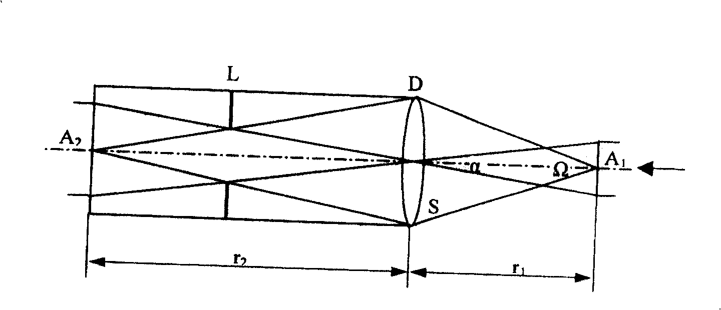
[0059] The principle diagram of the composition principle diagram of the flat-panel TV dual-lens chromaticity probe used in the light color automatic adjustment system of the present invention is as follows Figure 4 shown. The chromaticity probe is composed of two groups of lenses 41 and 42 , aperture bar 43 , three groups of color filters 44 , three photoelectric conversion devices 45 (such as silicon photocells), circuit board 46 , amplifier 47 and data transmission device 48 .

[0060] Red, green and blue three chromaticity sensing elements composed of three groups of glass color filters 44 and silicon photocells 45 are placed on the imaging surface, and their relative spectral sensitivity is corrected to the standard chromaticity observer spectrum recommended by the International Commission on Illumination. Stimulus value, when the red, green and blue chromaticity elements receive the light stimulus...


PUM


Abstract

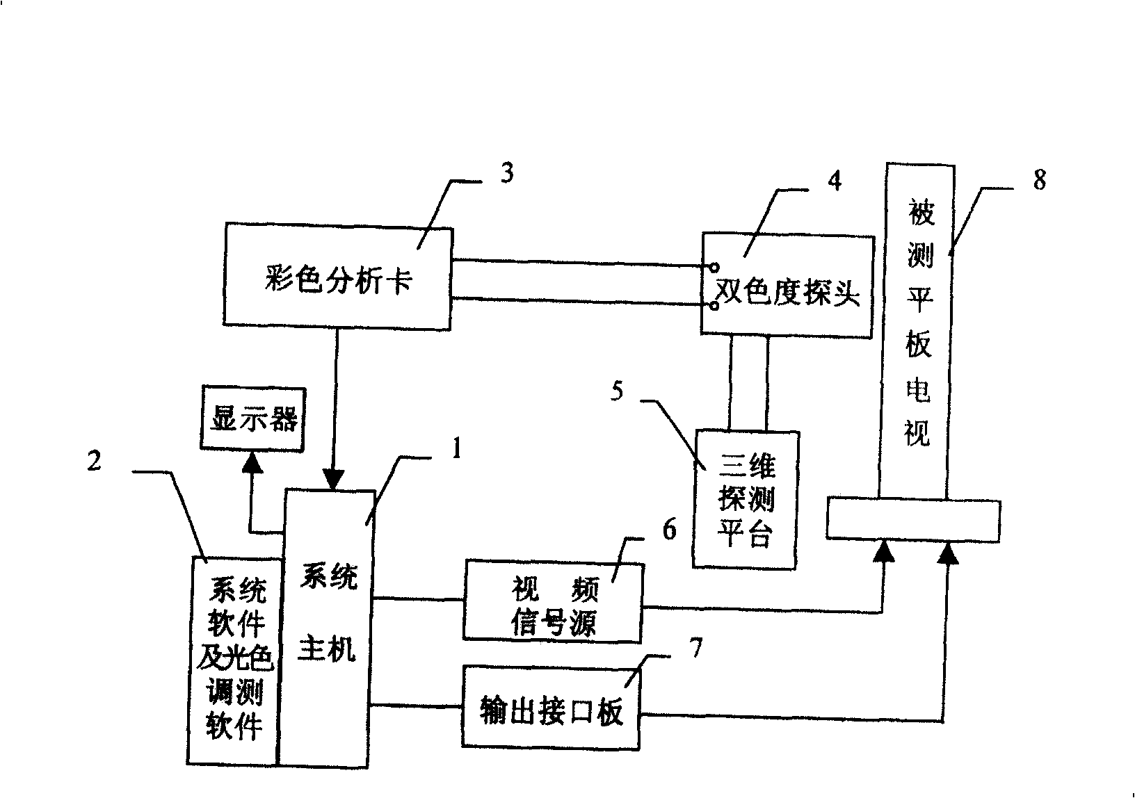
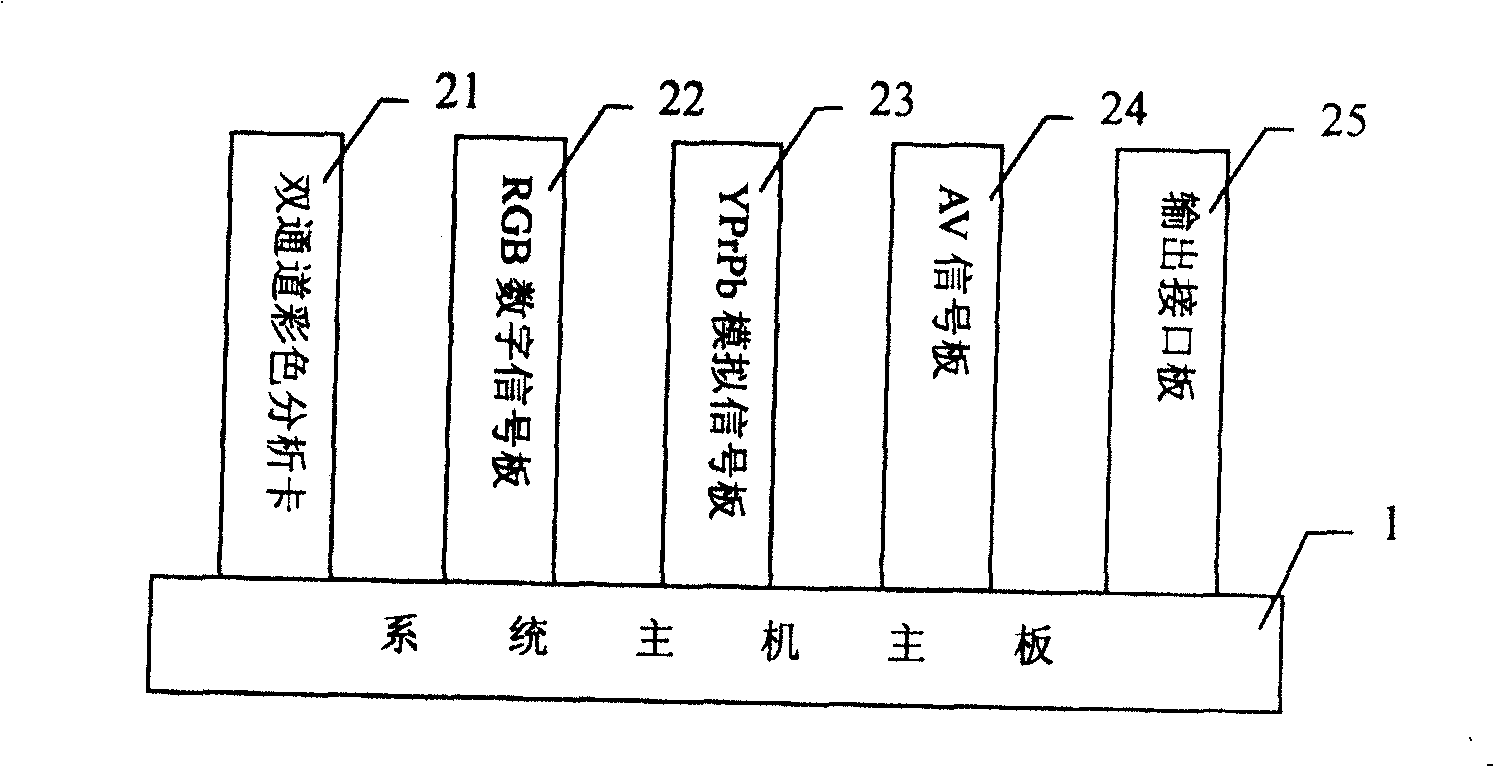
This invention puts forward a structure method for a photochromatic automatic test system used in panel TV sets such as PDP and LCD and its device, which integrates the color analysis card and digital and analog video signal boards physically on the host of the system reasonably. The system device is applied with a double channel color analyzing card and two optical image colority probes, the system is configured with a suit of 3-D detection platform, the two colority probes set on the platform can be adjusted in three dimensions freely on it, which meets the needs of photochromatic test of various sizes of panel TV sets and the needs of contacted or non-contacted measurement.

Description

[0001] Field [0002] The patent of the invention relates to the measurement and debugging technology of video display products, and is especially suitable for the composition method and device of the light color automatic debugging system of flat-panel TVs such as plasma (PDP) TVs and liquid crystal (LCD) TVs. Background technique [0003] Televisions using liquid crystal (LCD) and plasma (PDP) flat panel display devices are collectively referred to as flat panel televisions. As we all know, the salient features of flat-panel TVs are thin thickness, light weight, low power consumption, no flicker, and no radiation; in addition, flat-panel TVs have rich interfaces, which can receive cable TV radio frequency (RF), VCD video (AV), computer (RGB) ), digital DVI and analog YPrPb video signals. Because flat-panel TV can well meet the needs of digital TV, it has become the mainstream of the development of next-generation color TV and will become the most powerful competitor for the...

Claims


Application Information

Patent Timeline
Patent Type & Authority Patents(China)
IPC IPC(8): H04N17/00
Inventor 姚军吕颖琦张亮
Owner ZHEJIANG UNIV
Learn More