
Method and apparatus for crushing waste tyre

A pulverizer and gear set technology, which is applied in recycling technology, grain processing, mechanical material recycling, etc., can solve the problems of heavy workload and achieve the effects of small extrusion, low heat, and simple and reliable screen structure

Inactive Publication Date: 2009-02-04
顾洪 +1
View PDF7 Cites 2 Cited by
  • Summary
  • Abstract
  • Description
  • Claims
  • Application Information

AI Technical Summary

Problems solved by technology

[0005] In summary, the more reasonable solution for the existing rubber pulverizer is the roller pulverizer, which is provided with two rollers distributed in the way that the pair of rollers rotate inward, and the side surfaces of each roller can be smooth (mainly used Fine crushing of rubber), or several grooves formed by blades (mainly used for coarse crushing of rubber), the two rollers rotate under the drive of the driving mechanism during work, and the rubber block passes through the gap between the two rollers When crushed by rollers, the rubber block should be able to be fed conveniently and pass through the gap between the two rollers in time. This kind of pulverizer has a strong shearing and extrusion effect when the rubber is crushed, but it also needs a reasonable screen structure. , rubber fragments can be stuck between the blades, and the blades have a large workload, may need to be repaired or replaced in time, and need to have a compact structure

Method used


Image

  • Method and apparatus for crushing waste tyre
  • Method and apparatus for crushing waste tyre
  • Method and apparatus for crushing waste tyre

Examples


Embodiment Construction

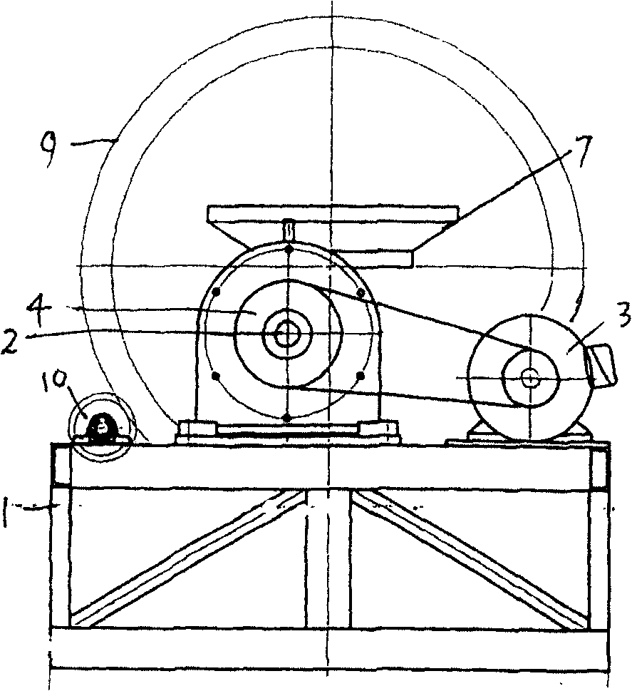
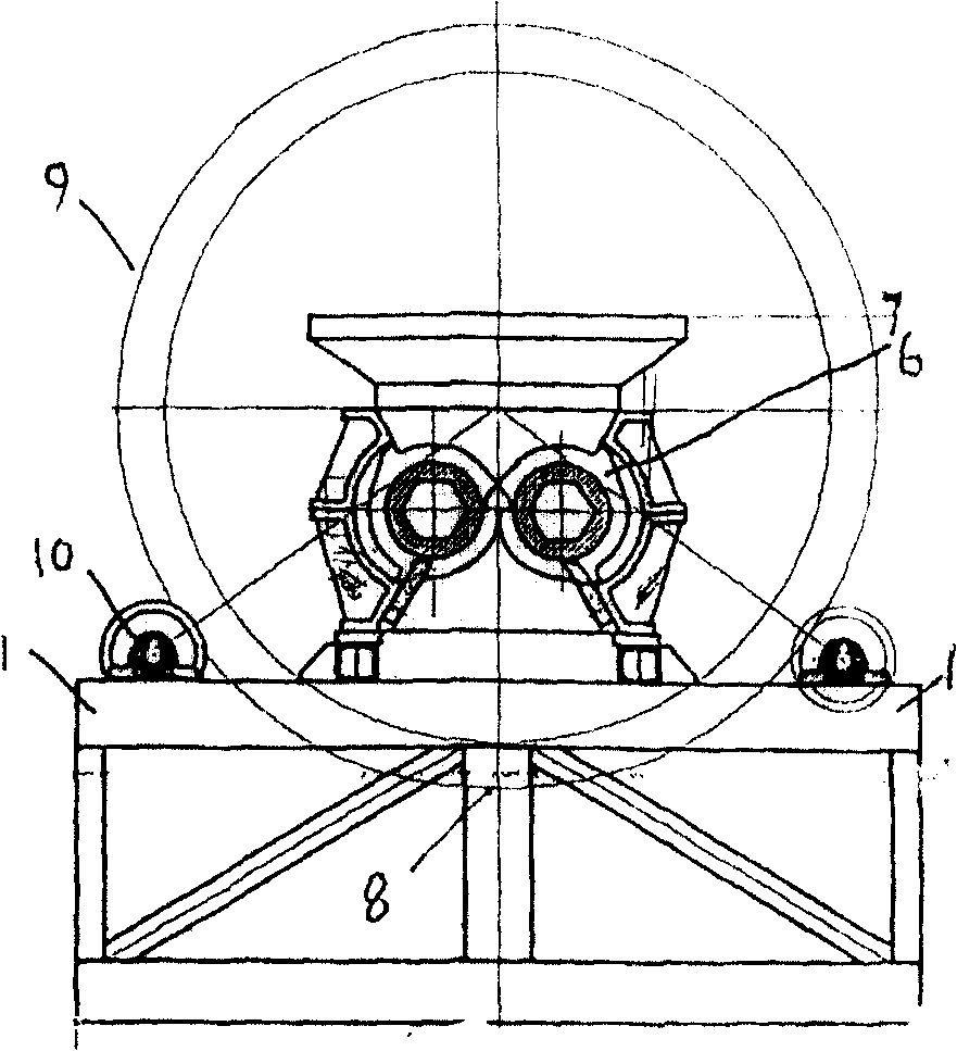
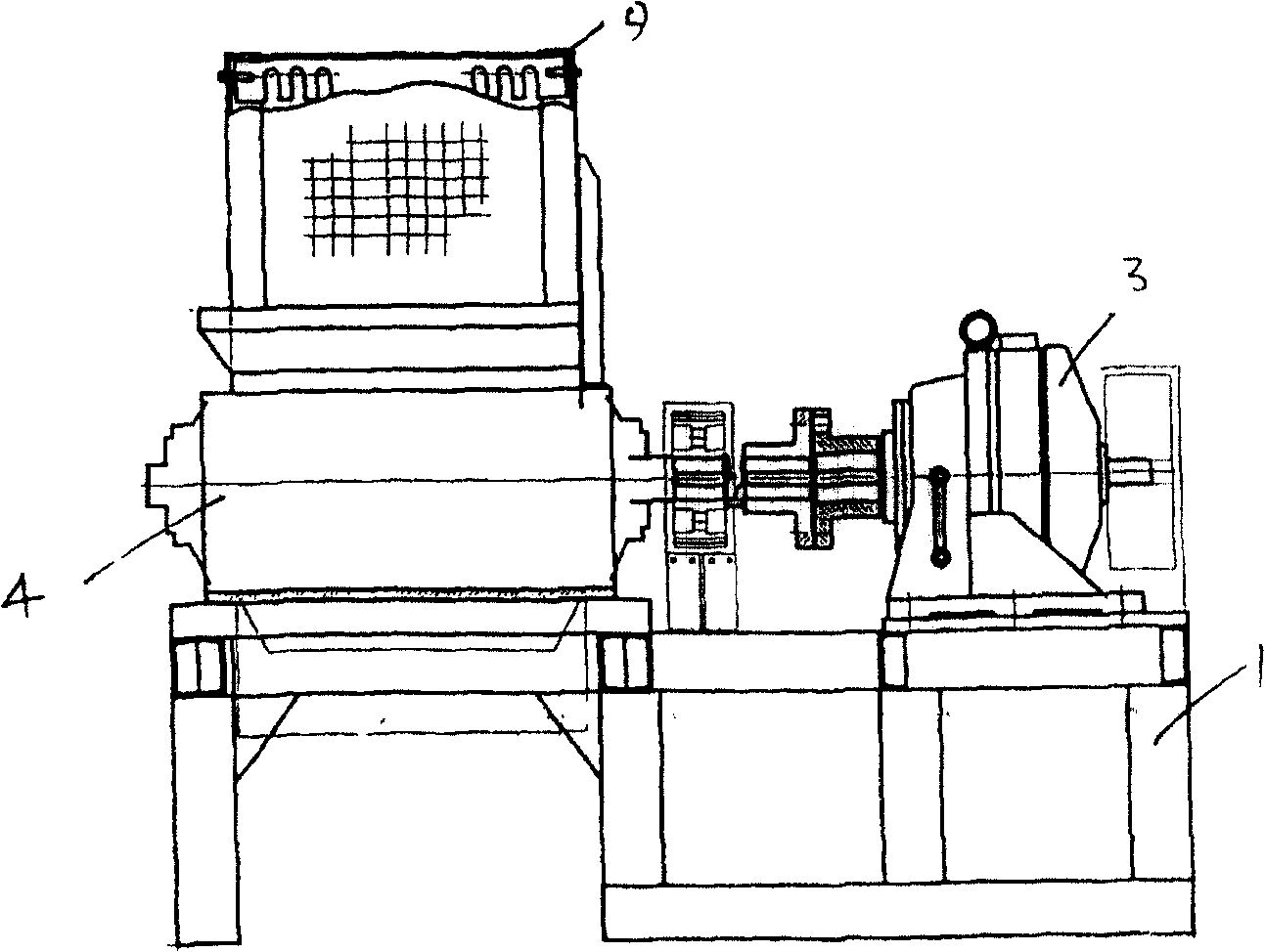
[0022] Referring to the accompanying drawings, the frame shaft seat is provided with two rollers formed by the shaft 5 which is distributed on the sheet cutter 6 according to the inward rotation of the pair of rollers, and the roller shaft is installed on the frame through the bearing seat. The two roller shafts are driven by the motor and the reducer (generally, the two rollers are driven at the same time); the present invention is provided with two rollers distributed according to the inward rotation of the pair of rollers, and the surface of at least one of the rollers is There are a number of sheet-like knives arranged vertically on the shaft, and the sheet-like knives on the two rollers are staggered (the gap between the two knives on the same roll is the protruding knives of the other roll) ), the right-angle knife edge between the staggered distribution of sheet-shaped cutters constitutes the cutting edge to cut rubber, and the width is the same as the width of the blade...


PUM

PropertyMeasurementUnit
widthaaaaaaaaaa

Abstract

The invention is concerned with a kind of rubber disintegrator. There are two roller canisters set in type of revolving on axis seat and they move inside of the roller. The axis of roller canister is fixed on frame of machine through the bearing seat, and the motor and reducer is droved by the revolving on axis seat and they move inside of the roller. The axis of roller canister is fixed on frame of mach axis of the two roller canisters. The said roller canister is made up of some slice type of drills on the axis with lengthways congruence and the drills of two roller canisters are interleaving. The roller canisters move to different directions and send the top of rubber block between the two roller canisters into the drills for cutting. The structure to exit of stuff is outer screen; with exit of stuff and the main part wrapped by the outer screen is the main body of the two roller canisters. The outer screen is a column and the side of it is the screen, the two bottom of it has circumferential rim and the bottom of each rim on the revolving axis seat is driven by transmission framework.

Description

technical field [0001] The invention relates to a large block crushing method and device for waste tires. Background technique [0002] Scrap tires are tough materials at room temperature, and the crushing consumes a lot of power, and it is difficult to achieve powder particles below 40 mesh. During conventional crushing, a large amount of heat is generated, causing the rubber powder to age and deform, and the quality deteriorates. The method of low-temperature pulverization utilizes the property that polymer materials such as rubber are brittle when they are below the glass transition temperature. At this time, they are easily pulverized into powdery substances by mechanical action, but the low-temperature method has high energy consumption; it is difficult to promote on a large scale application. Waste tires include ordinary bias tires and radial tires, ordinary bias tires, the cords of the adjacent layers of the buffer layer and the tire center line are arranged at an an...

Claims


Application Information

Patent Timeline
Patent Type & Authority Patents(China)
IPC IPC(8): B02C18/06B02C18/24B02C18/18B02C18/22B02C18/16B02C23/16B29B17/04
CPCY02W30/52Y02W30/62
Inventor 顾洪顾军
Owner 顾洪
Learn More