Single beam magneto-optic well system

A magneto-optical trap and single-beam technology, applied in the field of magneto-optical trap systems, can solve the problems of difficult adjustment of the optical path, complex structure, and large device volume, and achieve the effects of increasing practicability, small size, and convenient operation

Inactive Publication Date: 2009-02-25
WUHAN INST OF PHYSICS & MATHEMATICS CHINESE ACADEMY OF SCI
View PDF2 Cites 0 Cited by
  • Summary
  • Abstract
  • Description
  • Claims
  • Application Information

AI Technical Summary

Problems solved by technology

Compared with the single-beam light-trapping atom, the traditional six-beam light-trapping atom has the disadvantages of complex structure, large device volume, and difficult adjustment of the optical path.

Method used


Image

  • Single beam magneto-optic well system

Examples


Embodiment Construction

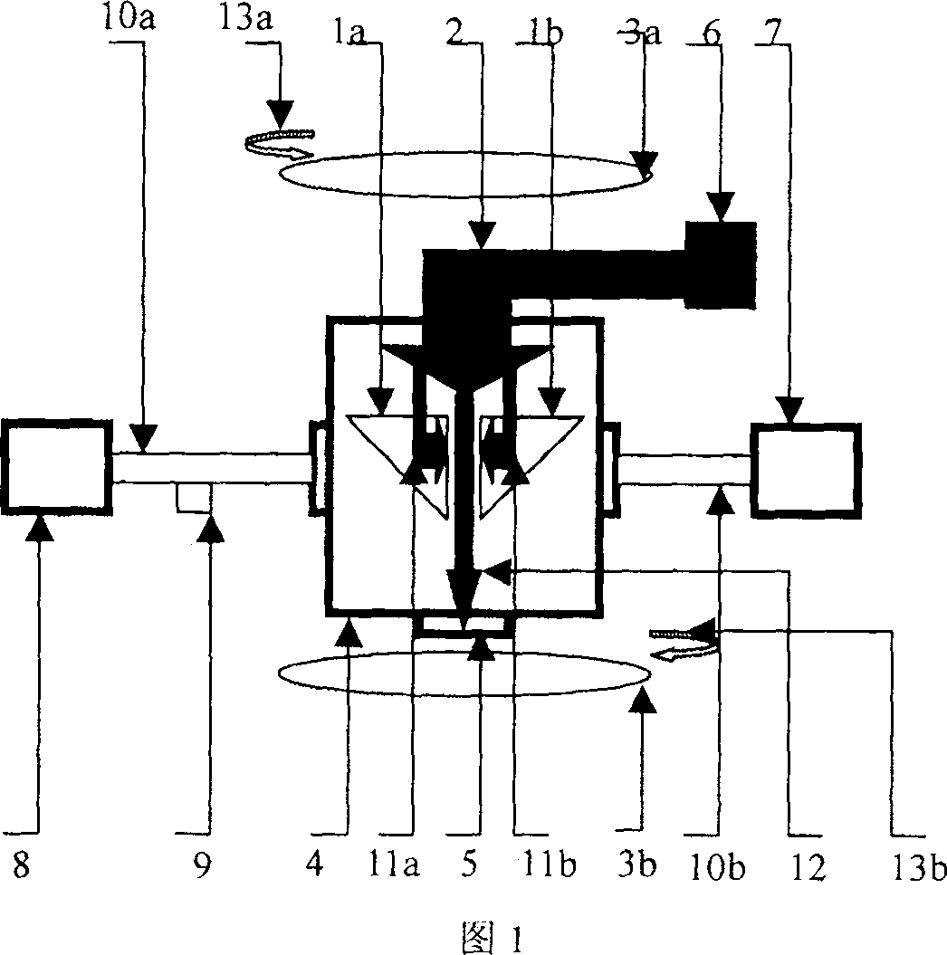
[0011] Below in conjunction with accompanying drawing, the present invention is described in further detail:

[0012] 1. The vacuum pump (8) is connected with a vacuum conduit (10a). The vacuum pump (8) includes a molecular pump and a mechanical pump, as well as bellows used for connecting the vacuum system. The ion pump (7) is connected with another vacuum conduit (10b). The ion pump (7) is a small sputtering ion pump. Both the vacuum conduit (10a) and the vacuum conduit (10b) are connected to the metal air chamber (4), and the connected windows are windows facing each other. The vacuum pump (8), that is, the molecular pump and the mechanical pump are used to pre-pump the entire device system. After the pre-pumping, the molecular pump and the mechanical pump can be turned off, and the ion pump (7) can be turned on to make the entire device system vacuum is maintained.

[0013] 2. The vacuum conduit (10a) is connected to the sample bubble (9), and the vacuum conduit (10a) ...


PUM

PropertyMeasurementUnit
wavelengthaaaaaaaaaa

Abstract

The disclosed single-beam magnetic trap system comprises: four same full-refraction lens connected with the confinement laser beam / beam-splitting, a couple of inverse Helmholtz coils linked to a metal gas room, a semiconductor laser connected with the confinement laser beam, a one-fourth wave plate with one surface coated reflector, and a vacuum guide pipe connected with a vacuum pump and an ion pump. This invention is simple and smart, operates easily, and has well reliability and stability.

Description

technical field [0001] The present invention relates to a magneto-optical trap system, in particular to a single-beam magneto-optic trap system, which is applicable to many scientific fields that use the basic characteristics of cold atoms to realize measurement and calibration, and have demands for cold atom sources. At the same time, it is also applicable to products that can be commercialized and industrialized by utilizing the characteristics of cold atoms, such as practical atomic clocks. Background technique [0002] Magneto-optical traps are also called Zeeman-shifted optical traps. It is a potential well formed by the combination of magnetic field and laser scattering force. In 1987, Bell Laboratories cooperated with MIT to realize the first magneto-optical trap for trapping sodium atoms. The basic principle is: three pairs of laser beams facing each other and perpendicular to each other meet at the center of the vacuum chamber containing the sample to be imprisone...

Claims


Application Information

Patent Timeline
Patent Type & Authority Patents(China)
IPC IPC(8): G02B17/04G02B17/02G02F1/29G01N21/25H03L7/26G04F5/14
Inventor 徐炳明王谨詹明生
Owner WUHAN INST OF PHYSICS & MATHEMATICS CHINESE ACADEMY OF SCI
Why Eureka
Try Eureka