Air separating device and method therefor

An air separation and air technology, applied in liquefaction, solidification, lighting and heating equipment, etc., can solve the problem of high power consumption

Active Publication Date: 2009-03-25
唐山瑞鑫液化气体有限公司
View PDF4 Cites 2 Cited by
  • Summary
  • Abstract
  • Description
  • Claims
  • Application Information

AI Technical Summary

Problems solved by technology

Using such a method and device to separate air to obtain oxygen, nitrogen and argon in different forms, especially liquid oxygen, nitrogen products and pressurized oxygen and nitrogen products, the power consumption per unit product is relatively high

Method used


Image

  • Air separating device and method therefor

Examples


Embodiment Construction

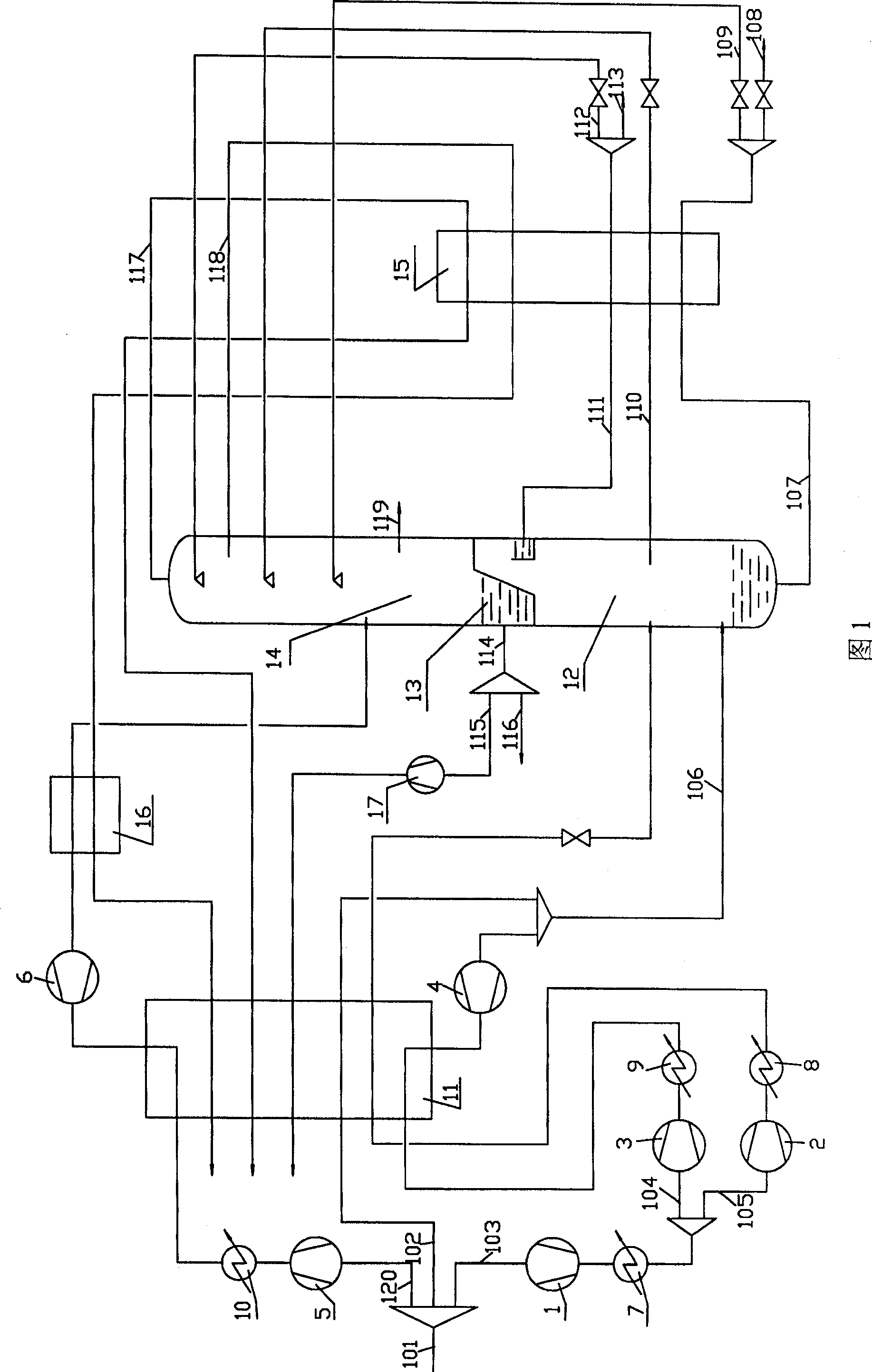
[0020] The present invention will be further described below in conjunction with accompanying drawing 1 and embodiment.

[0021] The air compressed by the compressor is cooled in the pre-cooling system and the raw material air 101 after removing harmful impurities such as water vapor, acetylene and carbon dioxide in the purification system is divided into three streams: the first stream 103 is compressed by the booster compressor 1, and the water cooler 7 is divided into two roads after cooling, one road 105 is further pressurized by the high-pressure supercharger 2, cooled by the water cooler 8, and then enters the main heat exchanger 11, where it is cooled and liquefied by the return gas, and then passed through the section The flow is depressurized and sent to the appropriate part of the lower tower 12 to participate in rectification. The other path 104 is supercharged by the supercharger 3 of the medium-pressure supercharged turbo expander, cooled in the water cooler 9, en...


PUM


Abstract

The invention relates to a method for using rectification at low temperature to separate air, and relative device. Wherein, said device comprises a booster (5), an expander (6), and a cooler (10) to form one low-temperature boost turbine expander, which will boost and cool another air to be reduced temperature, expanded and cooled in the main heat exchanger to be fed into the upper tower (14) of rectification tower for rectification. In the separation process, it uses different expanders as middle pressure and low pressure, which expand in different pressures and temperatures to supply cold energy to the separation process; the expanded air is fed into the upper and lower towers for rectification. The invention has lower unit electricity consumption as 2.5% reduced.

Description

technical field [0001] The present invention relates to a method and device for air separation, in particular to a method and device for separating air by rectification at low temperature. Background technique [0002] At present, the internal compression process using rectification to separate air at low temperature is a well-known industrial production technology. The usual method is: the air compressed by the compressor is cooled in the pre-cooling system and divided into two streams after removing harmful impurities such as water vapor and carbon dioxide in the purification system. One stream is pressurized and cooled and then divided into two streams. One stream enters the cold box after being pressurized again, compressed and cooled, and is cooled and liquefied in the main heat exchanger and sent to the lower tower after being decompressed. The other stream is used for expansion and refrigeration. The air flow, it enters the heat exchanger after being pressurized agai...

Claims


Application Information

Patent Timeline
Patent Type & Authority Patents(China)
IPC IPC(8): F25J3/04
CPCF25J3/04393F25J3/0409F25J3/04296F25J3/04412F25J3/04193F25J3/04303F25J3/04406
Inventor 江楚标付履南
Owner 唐山瑞鑫液化气体有限公司
Why Eureka
Try Eureka