An ARCP soft switch circuit with voltage clamp function

A voltage clamping and soft switching technology, applied in high-efficiency power electronic conversion, output power conversion devices, conversion equipment without intermediate conversion to AC, etc. Large volume and other problems, to achieve the effect of low cost, improve reliability and efficiency, and improve product competitiveness

Active Publication Date: 2009-07-01
VERTIV CORP
View PDF2 Cites 0 Cited by
  • Summary
  • Abstract
  • Description
  • Claims
  • Application Information

AI Technical Summary

Problems solved by technology

In this way, there will be P=1 / 2*L2*(I3)2 energy in the inductor L2 at the moment when the switch tube SW3 is turned off, and the original circuit does not provide a circuit that consumes this part of energy, nor does it provide a discharge path, so this part of the energy will generate a very high SPIKE peak voltage between the two ends of SW3—that is, between point A and point N, which is theoretically infinite, which is enough to damage the switch tube SW3 and cause the circuit to fail
[0004] The above problems are not only caused by the existence of parasitic capacitance C4: when the circuit input voltage, output load and other reference quantities change suddenly, or when the main switch tube SW1 and SW2 drive abnormally, and when the circuit just starts to start, the above problems will occur
But for the ARCP soft switching circuit topology, the situation is completely different: the inductance that causes the peak voltage across the switch tube is not leakage inductance or parasitic inductance, but the resonant inductance L2 used to realize soft switching. Usually this inductance is On the order of millihenry (for a single-phase 30KVA / 480V half-bridge inverter circuit, the inductance of this resonant inductance is 10 millihenry), the energy stored in the inductance that generates the peak voltage P=1 / 2*L2*(I3) 2 It is proportional to the inductance value. Since the inductance value in the ARCP circuit is an order of magnitude (1000 times) larger than the leakage inductance or parasitic inductance in the usual power electronic circuit, the energy in the inductor is correspondingly 1000 times larger under the same current times, if the RC or RCD snubber circuit used in general circuits is used, the required power of the snubber circuit capacitance and resistance should be increased by about 1000 times, which will make the snubber circuit very large, and because the RC and RCD snubber snubber circuits belong to Energy consumption type, that is, P=1 / 2*L2*(I3)2 is completely consumed, if the ARCP soft switch circuit also adopts the usual consumption absorption, it will not only cause the volume to be too large, but also cause low efficiency, making the soft switch circuit The switching circuit completely loses the use value of improving efficiency, and if the current I3 is considered to increase with the increase of power, it is very likely that the efficiency will not increase but decrease after the ARCP circuit is adopted.

Method used


Image

  • An ARCP soft switch circuit with voltage clamp function
  • An ARCP soft switch circuit with voltage clamp function
  • An ARCP soft switch circuit with voltage clamp function

Examples


Embodiment 1

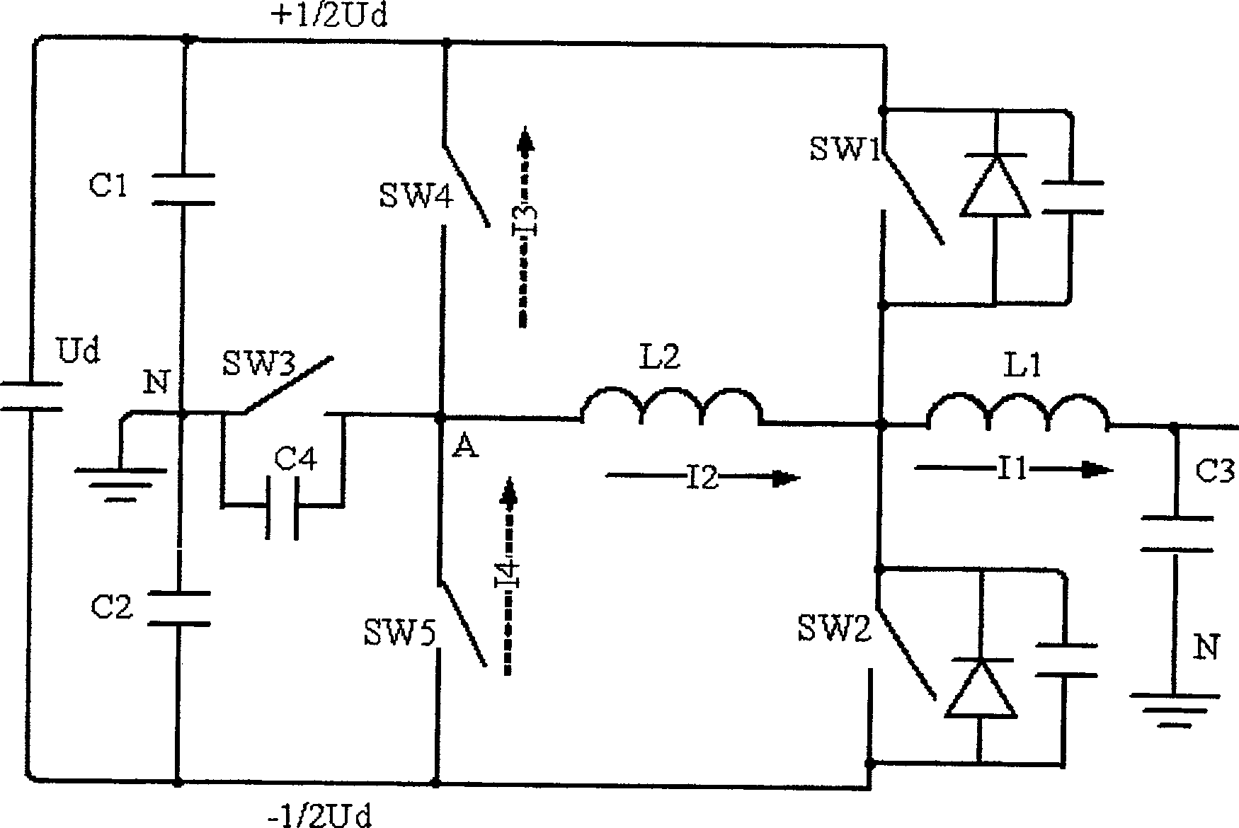
[0030] Such as Figure 4 As shown, in this embodiment, the fourth clamping freewheeling switch SW4 and the fifth clamping freewheeling switch SW5 use diodes, such as D1 and D2 in the figure.

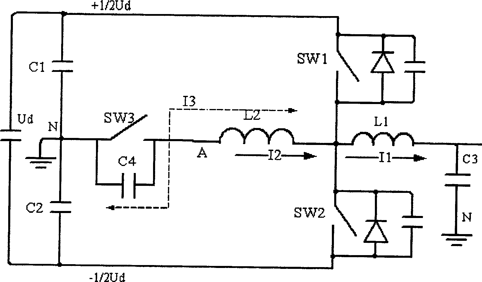
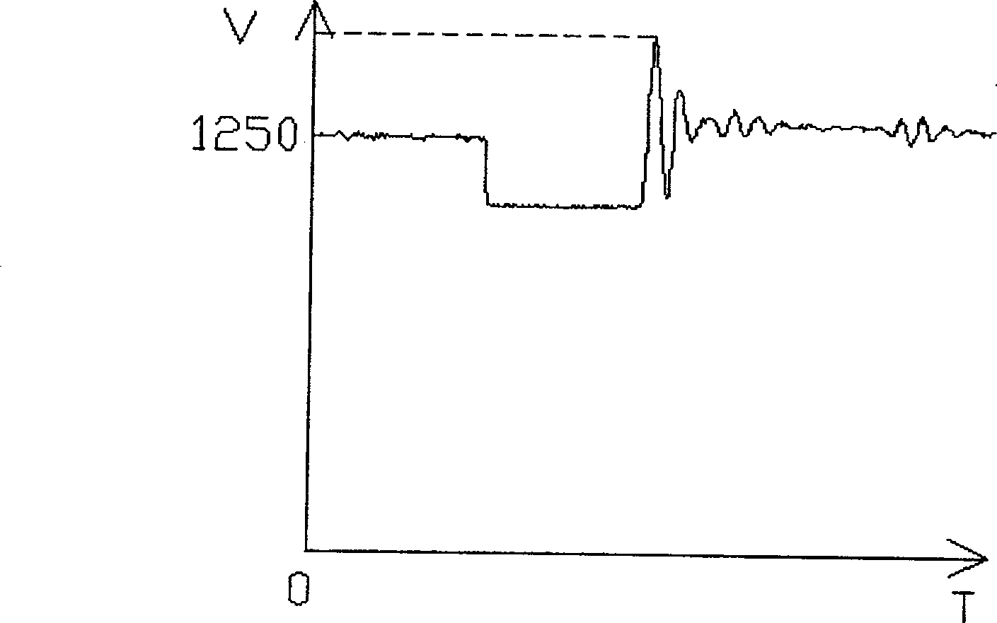
[0031] Such as Figure 5 As shown, when an ARCP soft switching circuit of the present invention is applied to a switching power supply in practice, when the auxiliary switch SW3 is turned off, or when a sudden change occurs in reference quantities such as circuit input voltage and output load, or the main switch tube SW1, When the SW2 drive is abnormal, or when the circuit just starts to start, the AN two-point voltage waveform. and figure 2 It can be seen from the comparison that the peak voltage of SPIKE has been significantly reduced.

Embodiment 2

[0033] Such as Figure 6 As shown, the difference between this embodiment and Embodiment 1 is that it also includes a sixth switch SW6, which is connected in series between the auxiliary switch SW3 and the resonant inductor L2, and the anode of the fourth clamp freewheeling switch SW4 and the fifth clamp continuous The cathode of the current switch SW5 is connected to the connection point of the auxiliary switch SW3 and the sixth switch SW6. The sixth switch SW6 can be a semiconductor device such as IGBT, MOSFET, GTO, SCR or the like. Wherein, the operation of the sixth switch SW6 and the auxiliary switch SW3 are completely synchronized. Its working principle is similar to that of the circuit in the first embodiment.

Embodiment 3

[0035] Such as Figure 7 As shown, the difference between the present embodiment and the second embodiment is that the cathode of the fifth clamp freewheeling switch SW5 is connected to the connection point of the resonant inductor L2 and the sixth switch SW6, and its anode is connected to the negative pole of the DC power supply. Wherein, the operation of the sixth switch SW6 and the auxiliary switch SW3 are completely synchronized. It works with Figure 6 The circuit shown is similar.


PUM


Abstract

The invention discloses an ARCP soft switch circuit with a voltage clamping function, which comprises a first main power switch, a second main power switch, a series branch composed of a third switch and a resonant inductance, and a fourth clamping freewheeling circuit switch and the fifth clamping freewheeling switch, wherein the fourth clamping freewheeling switch and the fifth clamping freewheeling switch are used to introduce excess energy in the series branch into the circuit loop when the third switch is turned off, One end of the fourth clamp freewheeling switch is connected to the positive pole of the DC power supply, and the other end is connected to a point between the third switch and the resonant inductor. One end of the fifth clamping freewheeling switch is connected to the negative pole of the DC power supply, and the other end is connected to the third switch One point is connected with the resonant inductance. The circuit of the invention can consume or absorb excess energy in the resonant inductance, reduce the peak high voltage of the ARCP circuit caused by the parasitic capacitance of the resonant inductance, improve the reliability and efficiency of the circuit, and have the advantage of low cost at the same time.

Description

technical field [0001] The invention relates to a soft switching circuit, in particular to an ARCP soft switching circuit with a voltage clamping function. Background technique [0002] Among the current soft switching circuits, there is an ARCP (auxiliaryresonant commutated pole) soft switching circuit in the form of "inductor + switch" series connection, which is favored by many switching power supply industry personnel because of its simple hardware circuit, easy control and good effect. Its circuit schematic diagram is as figure 1 shown. The main idea of ​​this circuit is to generate a resonant current I2 on the resonant inductance L2 through the auxiliary switch SW3 in the same direction as the current I1 of the main circuit filter inductance L1, through which the soft switching (ZVS) of the main power switch tubes SW1 and SW2 can be realized . [0003] From the analysis of the working principle of the circuit, it can be seen that for the auxiliary switch tube SW3, i...

Claims


Application Information

Patent Timeline
Patent Type & Authority Patents(China)
IPC IPC(8): H02M3/10H02M3/155
CPCY02B70/1491Y02B70/10
Inventor 肖学礼张晓飞张春涛
Owner VERTIV CORP
Why Eureka
Try Eureka