
Diode string structure

A diode string and diode technology, applied in the field of diode string structure, can solve the problems of affecting the normal operation of the circuit, affecting the response speed of high-speed circuits, and large structure area, and achieve the effects of small leakage current, small parasitic capacitance, and small structure area.

Active Publication Date: 2009-08-05
SHANGHAI HUAHONG GRACE SEMICON MFG CORP
View PDF5 Cites 0 Cited by
  • Summary
  • Abstract
  • Description
  • Claims
  • Application Information

AI Technical Summary

Problems solved by technology

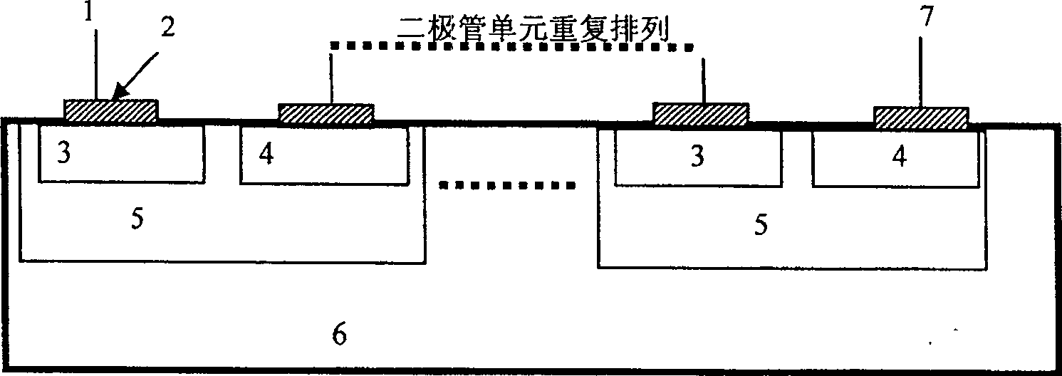
However, the conventional diode structure also has some disadvantages. For example, the minimum interval between each N-well implanted region of the structure is limited in size, and is larger than the required interval between the N-type implanted regions, so the structure area is relatively large; Another example is that there is a reverse parasitic diode between the conventional diode structure N-well injection region and the P-type silicon substrate. When the anode is biased, the P-type silicon substrate is at a low potential (grounded), so A large leakage current will be formed through the parasitic triode PNP, which will affect the normal operation of the circuit; also, due to the parasitic diode between the N-well injection region and the P-type silicon substrate in the conventional diode structure, there is also a parasitic capacitance effect, which will Affects the response speed of high-speed circuits

Method used


Image

  • Diode string structure
  • Diode string structure
  • Diode string structure

Examples


Embodiment

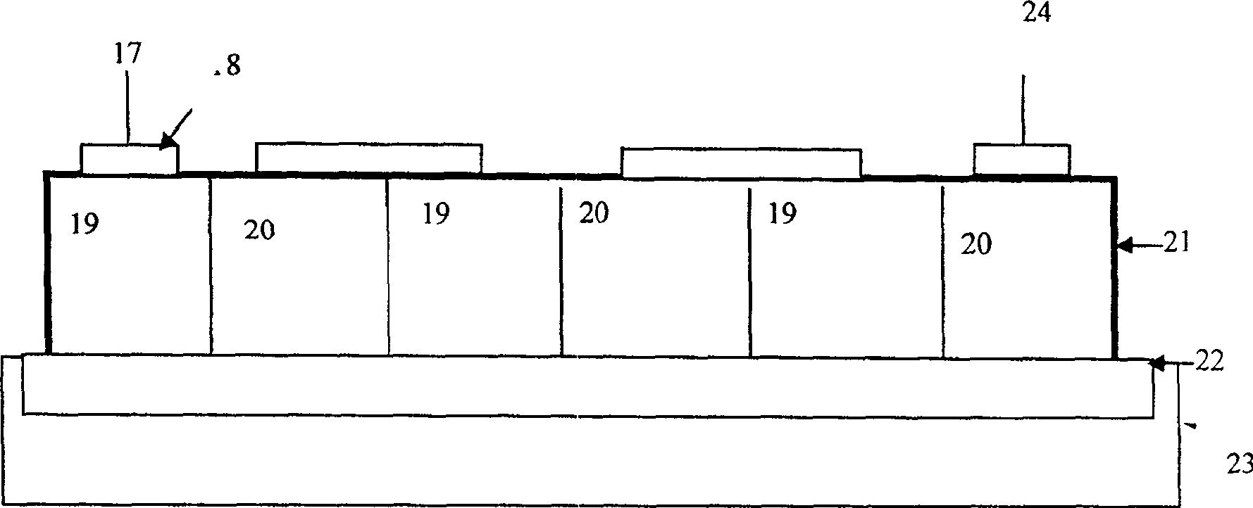
[0016] Such as image 3 As shown, it is a schematic cross-sectional view of a specific embodiment of the present invention. In this embodiment, three diode units form a diode string, wherein: 17, anode, 18, metal polysilicon, 19, P-type implantation region, 20, N-type Implantation area, 21, polysilicon, 22, field oxidation insulating layer, 23, silicon substrate, 24, cathode; Figure 4 yes image 3 The schematic diagram of the equivalent circuit. In the implementation, polysilicon in the existing CMOS process is used as the carrier of the three diodes shown in the figure, and three PN junctions are formed on the polysilicon by implanting different impurities, and the P-type implanted regions of two adjacent diode units are connected to the N-type The sides of the injection regions are connected and alternately arranged in a string, and the N-type injection regions and P-type injection regions of adjacent diode units are connected by metal oxide silicide of CMOS technology, s...


PUM


Abstract

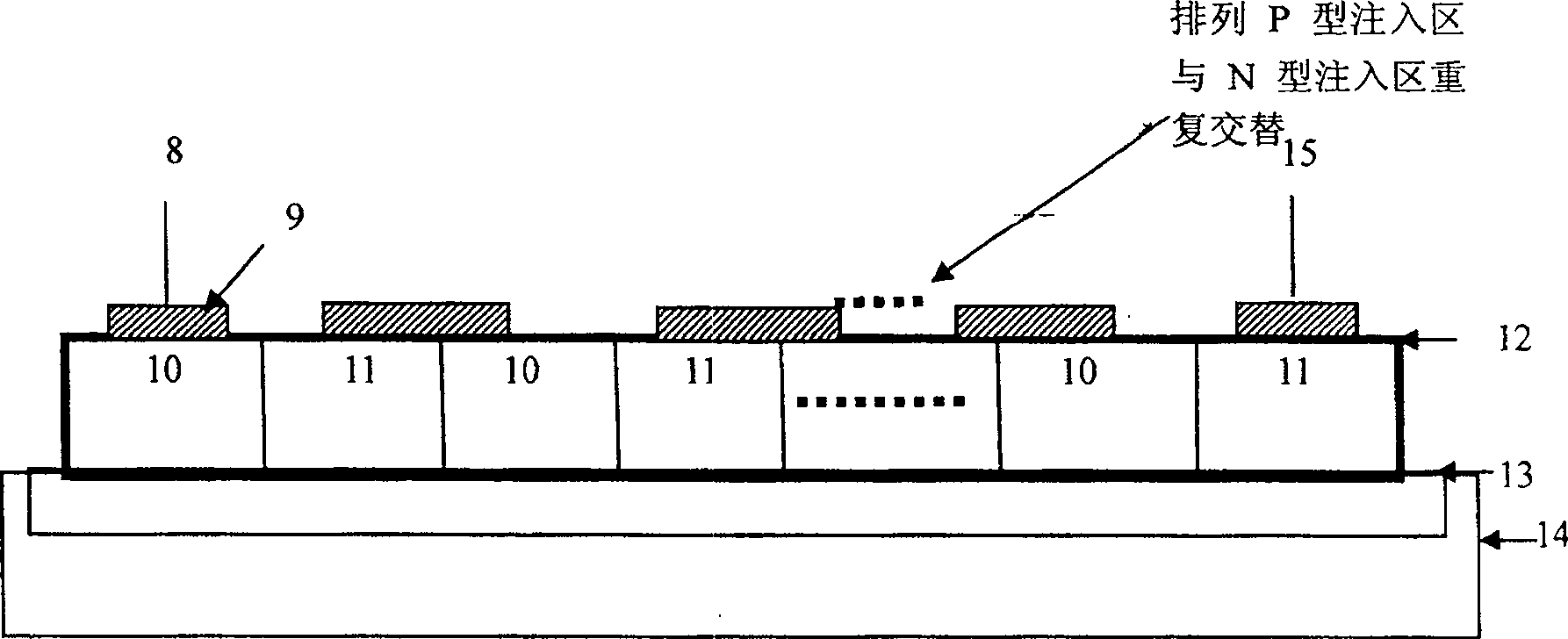
The invention discloses a polysilicon diode string structure. Polysilicon which is formed on a field oxide isolator (13) on a silicon substrate (14) is taken as the carrier for a plurality of diode units. The diode unit comprises a P-type injection region (10) and an N-type injection region (11). The P-type injection region and the N-type injection region of two neighboring diode units are alternately arranged in bunchiness, and two neighboring diode units are connected by metal oxide silicide (9). The diode string structure can be used in a radio frequency circuit or a common analog circuit of the circuit using forward diode string and an electrostatic protection circuit. Because the invention uses the polysilicon structure in design and the structure of the diode string is arranged on the field oxide isolator, compared to normal diode structure, the invention has the advantages of smaller structural area, smaller leakage current and smaller parasitic capacitance when realizing the diode string with the same number.

Description

technical field [0001] The invention relates to a diode string structure applied to analog circuits, electrostatic protection circuits, high-speed circuits, etc., in particular to a polysilicon diode string structure, that is, a structure in which polysilicon is used as a diode string. Background technique [0002] At present, in the actual design and application of analog circuits, electrostatic protection circuits and high-speed circuits, conventional diodes are popularly used as the basic structure of diode strings. This kind of diode string structure is generally formed on a silicon substrate. Its structure is as follows: figure 1 As shown, wherein: 1. Anode, 2. Metal polysilicon, 3. P-type implanted region, 4. N-type implanted region, 5. N-well implanted region, 6. P-type silicon substrate, 7. Cathode; shown The metal polycide 2 is used to reduce the resistance of the contact hole and the implanted area. As shown in the figure, this structure can be implemented on a si...

Claims


Application Information

Patent Timeline
Patent Type & Authority Patents(China)
IPC IPC(8): H01L27/08
Inventor 徐向明
Owner SHANGHAI HUAHONG GRACE SEMICON MFG CORP
Learn More