Fluidization-suspending two-stage type compound combustion device

A combustion device, a two-stage technology, is used in fluidized bed combustion equipment, fuel burning in a molten state, combustion chamber, etc., to achieve the effects of full combustion, high combustion efficiency, and reduced volatility

Inactive Publication Date: 2009-10-14
HARBIN INST OF TECH
View PDF9 Cites 2 Cited by
  • Summary
  • Abstract
  • Description
  • Claims
  • Application Information

AI Technical Summary

Problems solved by technology

[0004] In order to solve the problem that the bubbling fluidized bed combustion chamber and the suspension combustion chamber of the existing combustion device are integrated so that the two have mutual thermal influence and flow influence, it is impossible to fully burn the particle size or Combustion of two solid fuels with different activities, and then provides a fluidized-suspension two-stage composite combustion device

Method used


Image

  • Fluidization-suspending two-stage type compound combustion device
  • Fluidization-suspending two-stage type compound combustion device
  • Fluidization-suspending two-stage type compound combustion device

Examples


specific Embodiment approach 1

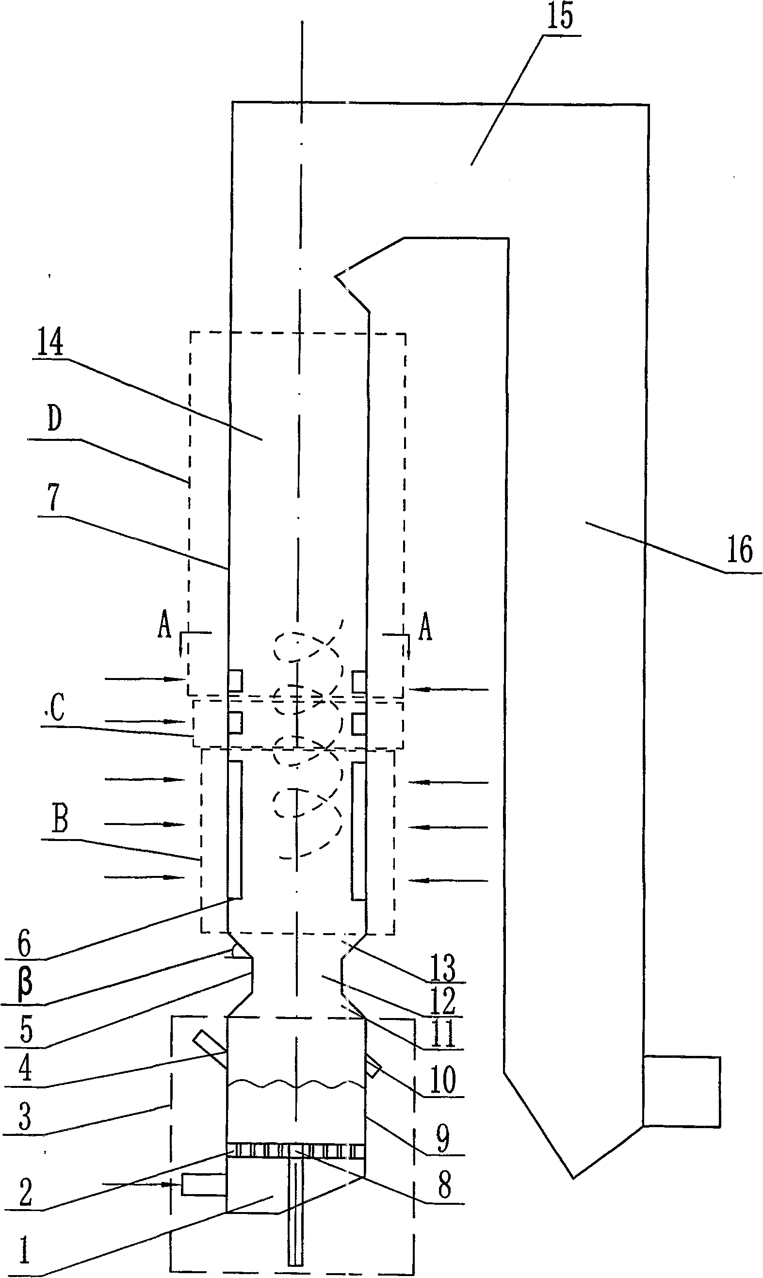
[0008] Specific implementation mode one: as figure 1 As shown, the fluidized-suspension two-stage composite combustion device of this embodiment consists of a bubbling fluidized bed low-temperature combustion chamber 3, a high-temperature vortex suspension combustion chamber 7, a variable-diameter chamber body 5, a horizontal flue 15, and a tail flue 16 components, the high-temperature vortex suspension combustion chamber 7 is located above the bubbling fluidized bed low-temperature combustion chamber 3, and the lower end of the high-temperature vortex suspension combustion chamber 7 and the upper end of the bubbling fluidized-bed low-temperature combustion chamber 3 pass through the variable-diameter chamber body 5 communicates, the lower end of the high-temperature vortex suspension combustion chamber 7 communicates with one end of the horizontal flue 15, and the other end of the horizontal flue 15 communicates with the upper end of the tail flue 16.

[0009] The combustion ...

specific Embodiment approach 2

[0010] Specific implementation mode two: as figure 1 As shown, the variable diameter section chamber body 5 in this embodiment is composed of a tapered section chamber body 11, a constant diameter section chamber body 12, and a gradually expanding section chamber body 13. The upper end of the tapered section chamber body 11 passes through the constant diameter section chamber body. The segment chamber body 12 is fixedly connected to the lower end of the expanding segment chamber body 13 . The variable-diameter chamber body 5 is mainly used to separate the bubbling fluidized bed low-temperature combustion chamber 3 and the high-temperature vortex suspension combustion chamber 7 into two relatively independent combustion spaces, organize the flue gas flow after the bubbling fluidized bed combustion, and increase The residence time of the particles, and the formation of a drop channel for the large slag generated by suspended combustion. The cross section of the variable diamete...

specific Embodiment approach 3

[0011] Specific implementation mode three: as figure 1 As shown, the included angle β between the chamber body 13 of the expanding section in this embodiment and the horizontal plane is greater than or equal to the angle of repose of the flow of slag particles. By changing the angle and size of the chamber body 5 of the reducing section, it can meet the needs of burning different fuels in the upper and lower parts. Other compositions and connections are the same as those in the second embodiment.


PUM


Abstract

A fluidized-suspension two-stage composite combustion device relates to a combustion device. The invention solves the problem that the bubbling fluidized bed combustion chamber and the suspension combustion chamber of the existing combustion device are integrated so that the two have mutual thermal influence and flow influence, and it is impossible to fully burn the particle size at the same time in the same combustion device. Or the problem of burning two solid fuels with different reactivity. The invention includes a bubbling fluidized bed low-temperature combustion chamber, a high-temperature vortex suspension combustion chamber, and a variable-diameter chamber body. The upper end of the low-temperature combustion chamber of the bubbling fluidized bed communicates with the chamber body through the variable diameter section; the multi-layer direct-flow burners are evenly distributed on the side wall of the suspension furnace body. The invention has the advantages of high combustion efficiency and sufficient combustion, and realizes that two solid fuels with different particle diameters or different combustion activities can be fully burned simultaneously in the same combustion device.

Description

technical field [0001] The invention relates to a combustion device, in particular to a combustion device capable of performing two combustion modes of fluidization and suspension at the same time. Background technique [0002] As a clean coal combustion technology with low pollution and good adaptability to coal types, fluidized bed combustion technology has been widely used in the past three decades. However, compared with the same type of pulverized coal furnace, this combustion method still has the disadvantages of high carbon content in fly ash and low combustion efficiency, which affects the promotion and application of this combustion technology. One of the reasons for the high carbon content of fly ash is that the fuel particle size distribution is relatively wide, and the small particle size particles in it do not have enough residence time in the combustion chamber. How to choose an efficient combustion method according to the particle size distribution of fuel an...

Claims


Application Information

Patent Timeline
Patent Type & Authority Patents(China)
IPC IPC(8): F23C6/04F23C10/00
Inventor 孙锐王正阳孙绍增朱群益赵广播邓启刚秦裕琨
Owner HARBIN INST OF TECH
Why Eureka
Try Eureka