
High-speed steel composite roller and casting method thereof

A technology of composite roll and high-speed steel, applied in the field of high-speed steel composite roll and its casting, can solve the problems of increased carbide content in core materials, high cost, complicated process, etc., and achieves inhibition of specific gravity segregation, strong accident resistance, combined good quality effect

Active Publication Date: 2009-10-21
INST OF METAL RESEARCH - CHINESE ACAD OF SCI
View PDF12 Cites 0 Cited by
  • Summary
  • Abstract
  • Description
  • Claims
  • Application Information

AI Technical Summary

Problems solved by technology

These technologies have not been promoted and applied due to limitations such as poor combination, poor accident resistance, complex process, high cost, and unreasonable structural design.
[0004] The high-speed steel roll adopts two-layer composite. Due to the large difference in the composition of the inner and outer layer materials, it is easy to cause the alloy elements of the outer layer material to melt into the inner layer during the actual centrifugal casting process, resulting in an increase in the carbide content of the core material, and even more carbide It is distributed in a network shape, so that the strength of the core material of the roll is reduced, and the roll is prone to breakage during the rolling process
In addition, due to the unreasonable selection of the material of the intermediate layer, the bonding defects such as graphite distortion at the bonding part, increase in carbide content, and carbide network formation are caused, and cracks are initiated at the bonding position during use, and crack propagation causes the working layer to fall off, etc.

Method used

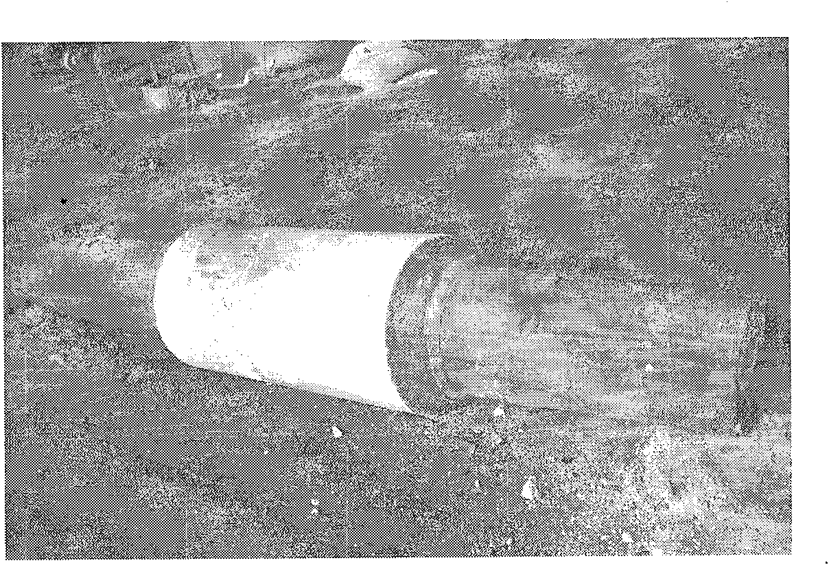
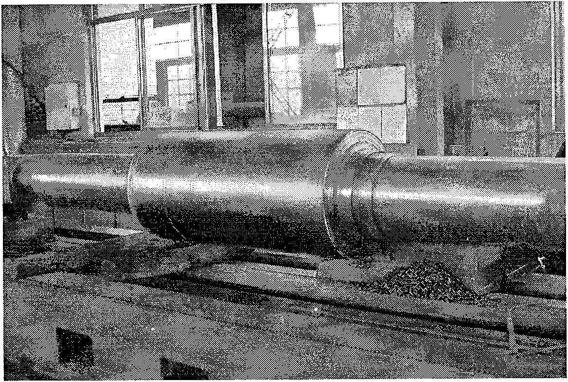
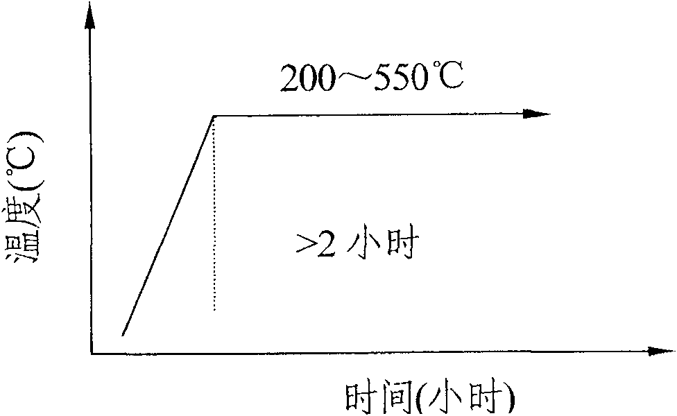

Image

  • High-speed steel composite roller and casting method thereof
  • High-speed steel composite roller and casting method thereof
  • High-speed steel composite roller and casting method thereof

Examples


Embodiment 1

[0058] According to the casting method of the high-speed steel composite roll of the present invention, a high-speed steel composite roll whose outer material is high-speed steel, the middle layer is the original molten iron of ductile iron, and the core material is ductile iron is produced. The diameter of the roll body is Φ500mm, and the thickness of the working layer is 50mm. The sampling composition of the roll body is shown in Table 1.

[0059] Table 1 Example 1 Roll body chemical composition (wt%, balance is Fe)

[0060] material

C

Si

mn

P

S

Ni

Cr

Mo

V

Al

outer layer

1.60

0.23

0.53

0.021

0.02

0.53

3.02

5.00

6.20

0.51

middle layer

3.0

1.8

0.4

0.03

0.034

--

--

--

--

--

Core

3.2

2.1

0.5

0.03

0.025

--

--

--

--

--

...

Embodiment 2

[0075] According to the casting method of the high-speed steel composite roll of the present invention, a high-speed steel composite roll whose outer material is high-speed steel, the middle layer is graphite semi-steel, and the core material is ductile iron is produced. The diameter of the roll body is Φ500mm, and the thickness of the working layer is 50mm. The sampling composition of the roll body is shown in Table 2.

[0076] Table 2. Embodiment 2 roll body chemical composition (wt%, balance is Fe)

[0077] material

C

Si

mn

P

S

Ni

Cr

Mo

V

Al

outer layer

2.6

1.0

0.33

0.024

0.021

0.93

6.00

8.03

9.87

0.2

middle layer

1.5

1.4

0.5

0.032

0.027

0.5

--

--

--

--

Core

3.3

2.1

0.5

0.032

0.025

--

--

--

--

--

[0078] Th...

Embodiment 3

[0092] According to the casting method of the high-speed steel composite roll of the present invention, a high-speed steel composite roll whose outer material is high-speed steel, the middle layer is graphite semi-steel, and the core material is ductile iron is produced. The diameter of the roll body is Φ500mm, and the thickness of the working layer is 50mm. The sampling composition of the roll body is shown in Table 3.

[0093] Table 3. Embodiment 3 roll body chemical composition (wt%, balance is Fe)

[0094] material

C

Si

mn

P

S

Ni

Cr

Mo

V

Al

outer layer

2.14

0.73

0.48

0.025

0.006

0.64

4.20

5.08

5.05

0.55

middle layer

1.0

2.0

0.8

0.035

0.030

0.2

--

--

--

--

Core

2.9

1.9

1.0

0.02

0.02

--

--

--

--

--

[0095] T...


PUM

PropertyMeasurementUnit
thicknessaaaaaaaaaa
thicknessaaaaaaaaaa
thicknessaaaaaaaaaa

Abstract

The invention belongs to the field of steel rolling manufacturing, in particular to a high-speed steel compound roll used in a strip mill in the steel rolling industry and a casting method thereof. The material of the outer layer of the composite roll is high-speed steel, the material of the middle layer is the original hot metal of ductile iron or graphite semi-steel, and the material of the core of the roll is ductile iron. The centrifugal compound casting process is adopted, and the roll is poured and formed three times. On the centrifuge, the outer layer and the middle layer metal materials are poured and formed at a constant centrifugal speed, and then the core metal of the roll is poured statically to make it finally formed; the high-speed steel composite of the present invention Compared with the previous double-layer or other three-layer composite high-speed steel rolls, the three-layer metallurgical bonding is good and the strength is high; the optimal selection of the material of the middle layer improves the strength of the bonding layer, and the carbides in the middle layer that affect the bonding performance are reduced. And effectively prevent the alloy elements in the outer high-speed steel from diffusing to the core, affecting the material properties of the core, and avoiding the cracking and falling off of the working layer during the heat treatment process and the rolling process.

Description

technical field [0001] The invention belongs to the field of steel rolling manufacturing, in particular to a high-speed steel compound roll used in a strip mill in the steel rolling industry and a casting method thereof. Background technique [0002] With the rapid development of the metallurgical industry, the continuous improvement of rolling technology, the continuous improvement of rolled material quality requirements, and the need for energy saving, energy saving, environmental protection, and sustainable development strategies, the rolling mill uses high performance, high wear resistance, and The requirements for accident-prone rolls are also becoming more and more urgent. High-speed steel rolls are favored due to their high wear resistance and long service life. However, there have always been various technical barriers in the manufacture of high-speed steel rolls in China, and it is difficult to move forward. More technologies are only in the research stage and cann...

Claims


Application Information

Patent Timeline
Patent Type & Authority Patents(China)
IPC IPC(8): C22C38/56C22C38/46B22D19/16B22D13/02
Inventor 栾义坤宋男男李殿中康秀红夏立军
Owner INST OF METAL RESEARCH - CHINESE ACAD OF SCI
Learn More