
Double-track four-crane conveyor

A transporter, double-track technology, applied in cranes, transportation and packaging, etc., can solve problems such as difficulty in dragging the bracket, difficult to control the position, and insufficient installation of the bracket in place, so as to achieve reliable lifting stability, low relocation cost, and structural integrity. simple effect

Inactive Publication Date: 2009-12-09
张常年
View PDF7 Cites 0 Cited by
  • Summary
  • Abstract
  • Description
  • Claims
  • Application Information

AI Technical Summary

Problems solved by technology

[0003] (1) The underground floor is soft or has a bottom drum phenomenon, and the weight of the bracket is heavy, so it is difficult to drag the bracket;
[0004] (2) When the bracket is dragged or towed to the flatbed truck, its moving direction is not easy to control, and the bracket needs to be adjusted separately on the flatbed truck;
[0005] (3) When the bracket is on the flatbed truck, a steel slope is required as the drag bridge deck. Since the bracket moves along the steel slope during dragging, its frictional resistance is large, sparks are easily generated, and gas explosions are prone to occur, resulting in safety of personnel and mines;
[0006] (4) The relocation speed is slow. If the floor of the working surface is soft, it usually takes about 30 days to relocate a working surface, and it is also difficult to install again. The work efficiency is low, which increases the cost of relocation. At the same time, it produces less coal and the overall efficiency decreases;
[0007] (5) Due to the slow speed of relocation, it is easy to cause the goaf to be unable to be topped in time, which affects the safety of workers and equipment, and the loss is immeasurable
[0008] (6) It is difficult to control the position when the bracket is dragged or the bracket is not installed in place. It takes a lot of time to adjust the position, wasting manpower and material resources

Method used


Image

  • Double-track four-crane conveyor
  • Double-track four-crane conveyor
  • Double-track four-crane conveyor

Examples


Embodiment Construction

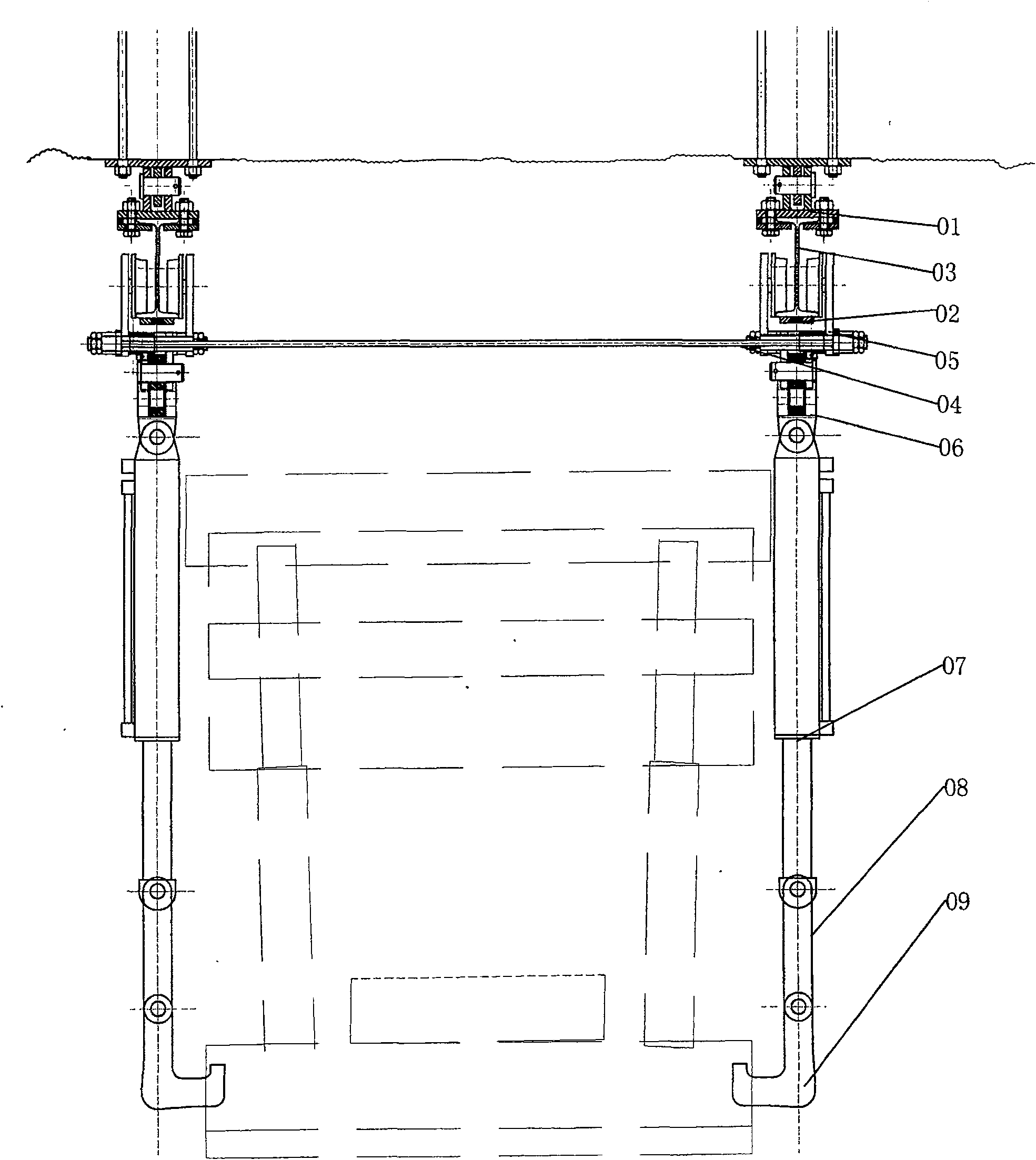
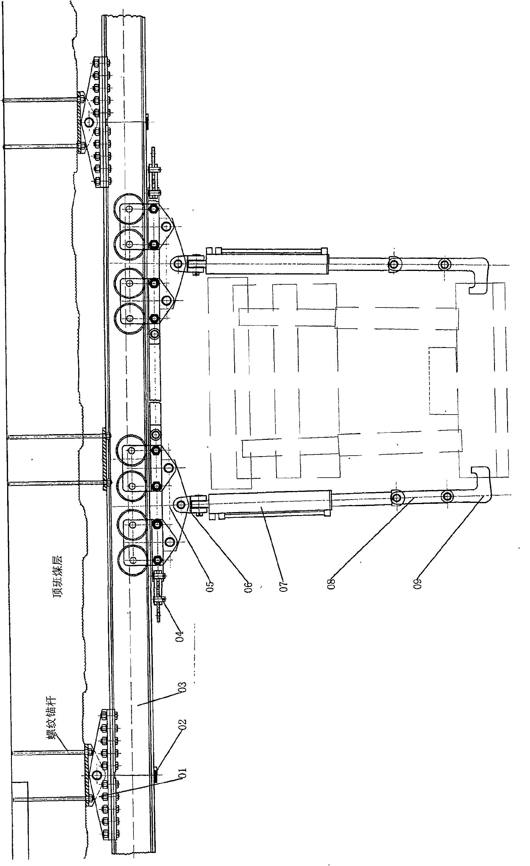
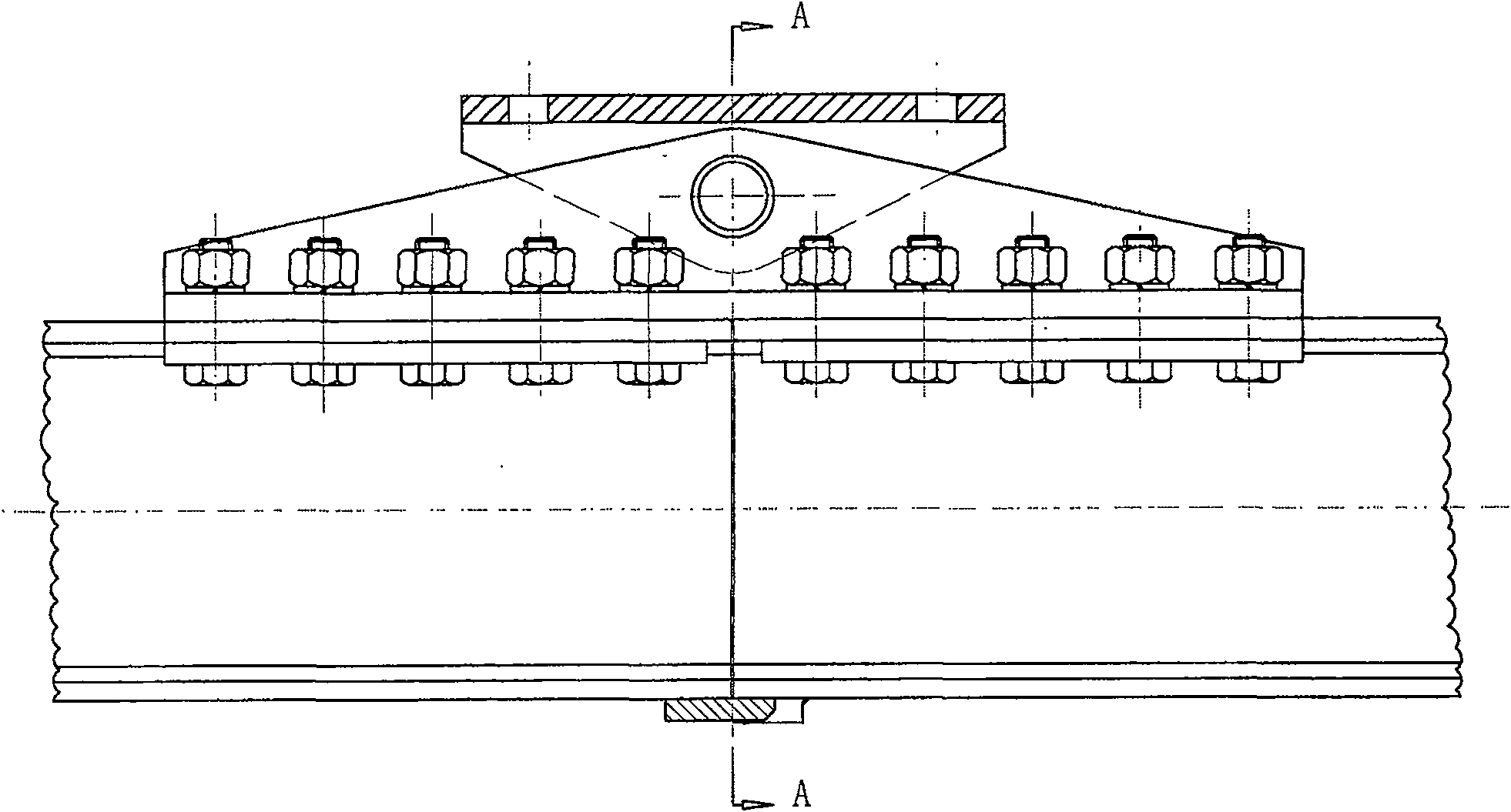
[0020] Accompanying drawing is embodiment of the present invention.

[0021] Below in conjunction with accompanying drawing, content of the invention will be further described:

[0022] refer to figure 1 , figure 2 As shown, the upper edge of the track 03 is connected to the track fixing mechanism 01, and the lower edge is slidingly connected to the wheel set mechanism 05 and the traction mechanism 04. The wheel set mechanism 05 is connected to the cross joint 06, and the cross joint 06 is connected to the lifting cylinder 07. , the piston rod in the lifting cylinder 07 is connected with the hook connecting pull 08, the hanging hook connecting pull 08 is connected with the lifting hook 09, the track fixing mechanism 01 is connected with the anchor rod device, and the anchor rod device is fixedly connected with the coal seam roof. The lifting cylinder 07 and the piston rod are connected with the lifting hook through the hydraulic system, and the lifting cylinder 07 and the p...


PUM


Abstract

The invention discloses a two-track four-lift conveyor. The upper edge of the track is connected with the track fixing mechanism, and the lower edge is slidingly connected with a wheel set mechanism and a traction mechanism. The wheel set mechanism is connected with the cross mechanism, the cross mechanism is connected with the lifting cylinder, and the piston rod in the lifting cylinder is connected with the hook. The pulley is connected, the hook connecting plate is connected with the hook, the track fixing mechanism is connected with the anchor device, and the anchor device is fixedly connected with the coal seam roof. The structure is simple, the use is convenient, the installation and disassembly of the hydraulic support is fast, the lifting stability is reliable, the relocation cost is low, and the time is short. In the past, it took about 30 days to relocate a working face, but it only takes 5-8 days to complete the relocation by using the present invention. The efficiency is more than 5 times, and it can be widely used in coal mine fully mechanized mining face.

Description

technical field [0001] The present invention relates to a kind of hoisting mechanical equipment, in particular to a kind of double-rail four-lift handling machine. Background technique [0002] There are many types of hoisting machinery on the market, and more than 99% of them are used to lift materials on the ground. It is not limited by any space and terrain. However, it is obvious that the above-mentioned equipment is used in mines. Powerless, because the space and terrain under the mine are limited, especially the hydraulic support used in the coal mining face, each support weighs about 20 tons, and there are more than 100 hydraulic supports in a coal mining face, currently installed or dismantled Most of the hydraulic supports are first dragged to the floor by a winch, and then pulled on a flatbed truck to be transported to a new working surface for reinstallation. There are the following disadvantages in relocating hydraulic supports in this way: [0003] (1) The unde...

Claims


Application Information

Patent Timeline
Patent Type & Authority Patents(China)
IPC IPC(8): B66C25/00
Inventor 张常年
Owner 张常年
Learn More