Dynamic property test analysis system for DC hybrid contactor reliable life experiment
A technology of dynamic characteristics and test analysis, applied in circuit breaker testing, instruments, measuring electricity, etc., can solve the problems of incomplete and inaccurate data collection, inability to collect and transmit data in real time, etc., to achieve full automation and storage. Manage and improve the effect of precision
- Summary
- Abstract
- Description
- Claims
- Application Information
AI Technical Summary
Problems solved by technology
Method used
Image
Examples
specific Embodiment approach 1
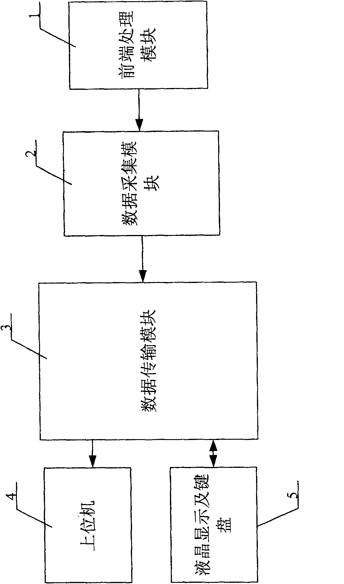
[0025] Specific implementation mode one: the following combination figure 1 Describe this embodiment in detail, and this embodiment includes a front-end processing module 1: an analog signal for generating various parameters;
[0026] Data acquisition module 2: used to collect the analog signal generated by the front-end processing module, and convert the analog signal into a digital signal;
[0027] Data transmission module 3: consists of core control and data transmission modules, controls the data acquisition module, receives the data transmitted by the data acquisition module, and transmits the data;
[0028] Host computer 4: receive the data transmitted by the data transmission module, and perform analysis and processing of software design;
[0029] Liquid crystal display and keyboard 5: The liquid crystal display realizes real-time refresh of the current collected data, and can display abnormal data; set the frequency of collection and the time of experiment through key...
specific Embodiment approach 2
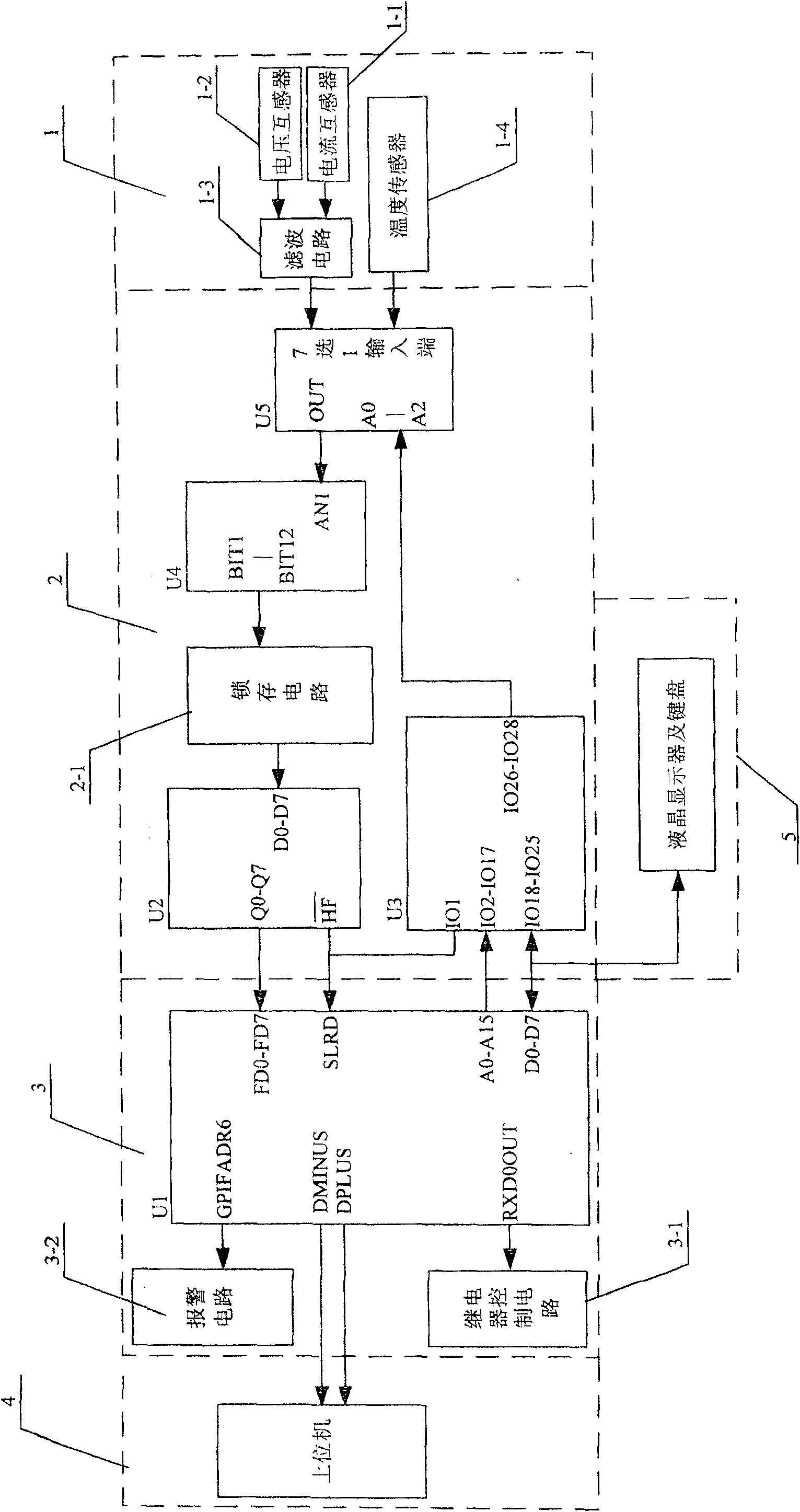
[0031] Specific implementation mode two: the following combination figure 2 Describe this embodiment in detail. The difference between this embodiment and the first embodiment is that the front-end processing module 1 is composed of a current sensor 1-1, a voltage sensor 1-2, a filter circuit 1-3 and a temperature sensor 1-4. 1-1 and the output end of the voltage sensor 1-2 are connected to the input end of the filter circuit 1-3, and other components and connections are the same as those in the first embodiment. The current and voltage of the coil and contacts of the DC hybrid contactor are collected by the current sensor and the voltage sensor. For the data of the current sensor, it is converted into a unified voltage signal with a precision resistor. All the collected voltage signals are filtered within a certain frequency range through the filter circuit to remove part of the interference components, and the signals are provided to the data acquisition module.
specific Embodiment approach 3
[0032] Specific implementation mode three: the following combination figure 2 Specifically illustrate this embodiment, the difference between this embodiment and specific embodiment two is: data acquisition module 2 is made up of analog switch chip U5, AD conversion chip U4, latch circuit 2-1, FIFO storage chip U2 and CPLD chip U3, The input terminal of the analog switch chip U5 is connected to the output terminal of the front-end processing module 1, the output terminal OUT of the analog switch chip U5 is connected to the analog signal input terminal AN1 of the AD conversion chip U4, and the address bus A0-A2 of the analog switch chip U5 is connected to The first IO bus IO26-IO28 of the CPLD chip U3, the output terminal BIT1-BIT12 of the AD conversion chip U4 is connected to the input terminal of the latch circuit 2-1, and the output terminal of the latch circuit 2-1 is connected to the input terminal of the FIFO memory chip U2 D0-D7, the control signal terminal HF of the FI...
PUM
 Abstract
Description
Claims
Application Information
 - R&D
- Intellectual Property
- Life Sciences
- Materials
- Tech Scout
- Unparalleled Data Quality
- Higher Quality Content
- 60% Fewer Hallucinations
Browse by: Latest US Patents, China's latest patents, Technical Efficacy Thesaurus, Application Domain, Technology Topic, Popular Technical Reports.
© 2025 PatSnap. All rights reserved.Legal|Privacy policy|Modern Slavery Act Transparency Statement|Sitemap|About US| Contact US: help@patsnap.com


