Power device in electronic optical path system of electronic bundle impact furnace

A technology of electron beam bombardment and optical path system, which is applied in the direction of electric heating devices, electric furnaces, furnaces, etc., can solve problems such as failure to meet the requirements of smelting process, random fluctuation of accelerating voltage, and electron beam off-target, etc., and achieve fast dynamic follow-up performance indicators and easy adjustment Effect

Inactive Publication Date: 2010-01-20
GUILIN UNIV OF ELECTRONIC TECH
View PDF6 Cites 0 Cited by
  • Summary
  • Abstract
  • Description
  • Claims
  • Application Information

AI Technical Summary

Problems solved by technology

[0005] The main power supply (acceleration power supply) of the electron beam bombardment furnace adopts open-loop control and three-phase mains full-wave power supply to achieve green power supply and energy-saving operation effects, but the acceleration voltage will fluctuate randomly during operation. In this case, the independently controlled Electronic optical circuit power supply system will not meet the requirements of smelting process
[0006] If the electron beam bombardment furnace breaks down (such as high-voltage discharge phenomenon) and the acceleration voltage changes greatly, the change of the focus position and deflection angle of the electron beam may exceed the allowable range, resulting in adverse consequences of the electron beam missing the target

Method used


Image

  • Power device in electronic optical path system of electronic bundle impact furnace
  • Power device in electronic optical path system of electronic bundle impact furnace
  • Power device in electronic optical path system of electronic bundle impact furnace

Examples


Embodiment Construction

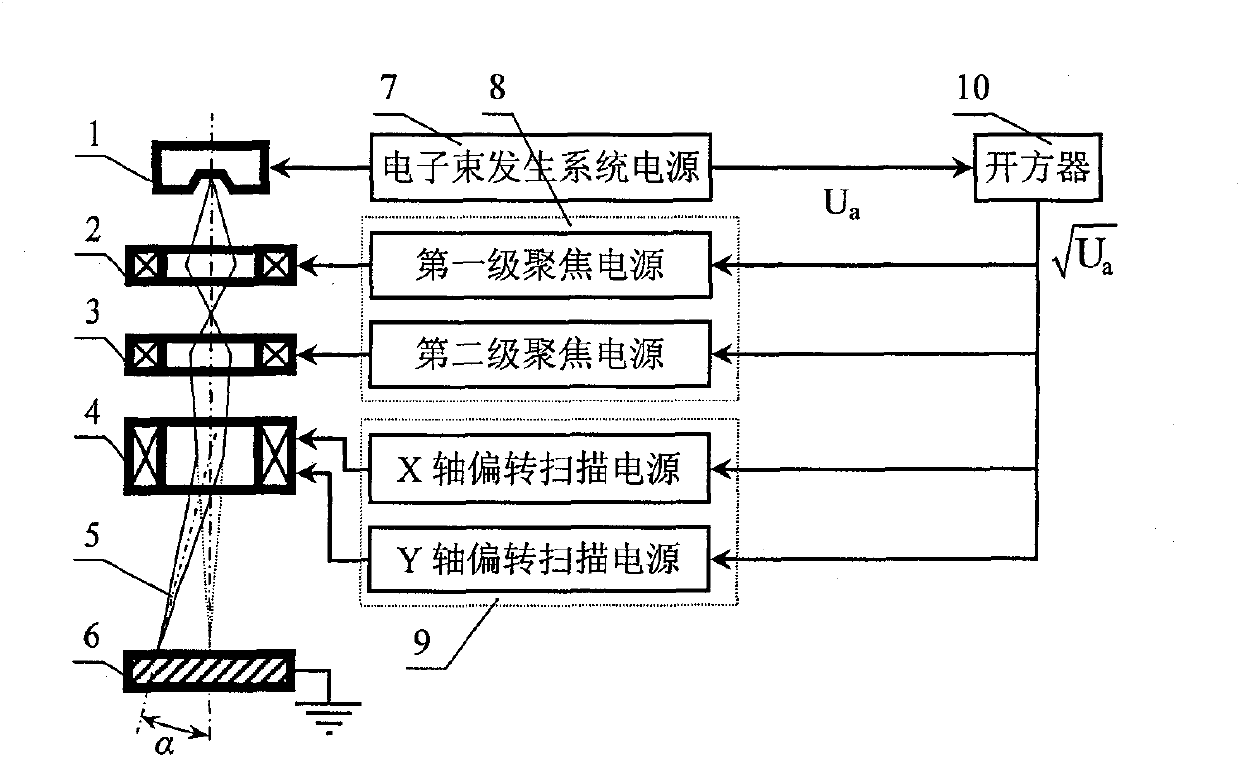
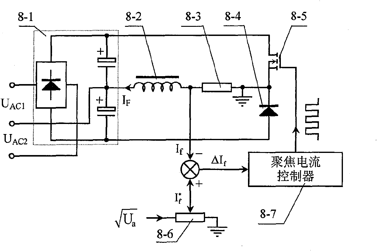
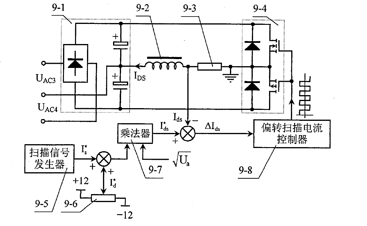
[0021] Example of the power supply device for the electron beam system of the electron beam bombardment furnace of the present invention figure 1 As shown, the electron beam generated by the electron beam generating system 1 is focused and deflected and scanned by the electron optical system of the electron beam bombardment furnace, and then the electron beam is reasonably distributed on the target 6 for heating and melting. The electron beam optical system has a first focusing coil 2 and a second focusing coil 3 as a focusing magnetic lens, and a deflection scanning coil 4 . The structure of the focus power supply 8 of the two focus coils 2, 3 is the same as the control law of the focus current. The deflection scan coil 4 has two pairs of coils with magnetic poles, which are symmetrically installed in the electron gun. The magnetic field of one pair of magnetic poles deflects the electron beam along the X-axis of the radial plane, and the magnetic field of the other pair of m...


PUM


Abstract

The invention discloses a method for controlling a power supply of an electron-optical circuit system of an electron beam furnace and a power supply device. The method takes the extraction value of an acceleration voltage sampling signal of a power supply of an electron beam generating system as a control signal for a focusing and deflection scanning power supply and the amplitude of a focusing and deflection scanning current changes linearly according to the control signal, which ensures that the operation parameter of the electron-optical circuit system is free from the influence of the fluctuation of the acceleration voltage. The power supply device has the acceleration voltage sampling signal connected with a square root extractor first and then connected to a focusing and deflection scanning power supply control circuit, and adopts a hysteresis-band current tracking pulse modulation controller to maintain a small up and down oscillation amplitude of a working current based on an expected value. An extraction value signal of the acceleration voltage sampling signal is used to control a focusing current, and a general control signal which is the produce of a deflection scanning integrated signal and the extraction value of the acceleration voltage sampling signal is used to control deflection scanning current, so the focusing and deflection scanning region of the electron beam is not influenced by the acceleration voltage, and in event of failure, the change of the focusing and deflection scanning region of the electron beam is controlled in a permitted range.

Description

(1) Technical field [0001] The invention relates to electron beam electric heating equipment, in particular to an electron beam bombardment furnace electronic optical path system power supply device. (2) Background technology [0002] The electron beam bombardment furnace is an electrothermal equipment that uses the heat energy generated when high-speed electrons bombard the charge for melting and heating. Compared with other vacuum melting furnaces, it has high power density and can be used for smelting and refining precious, rare and refractory metals. The vacuum degree in the furnace is high, and it is easy to prepare various high-purity materials or Special alloys and used for smelting high-quality special steel and titanium waste recycling, etc. In addition, it also has the advantage of no refractory material pollution to the charge. [0003] The key technology of the electron beam bombardment furnace is the electron beam generator (electron gun) and its power supply. ...

Claims


Application Information

Patent Timeline
Patent Type & Authority Patents(China)
IPC IPC(8): H05B7/144C21B11/10C21C5/52C22B4/00
CPCY02P10/20Y02P10/25
Inventor 韦寿祺莫金海李海标
Owner GUILIN UNIV OF ELECTRONIC TECH
Why Eureka
Try Eureka