Off-magnet patient scan positioning

A positioning system and positioning method technology, applied in the field of medical imaging technology, can solve problems such as movement discomfort, and achieve the effect of reducing delay period and improving throughput

Active Publication Date: 2010-02-24
KONINK PHILIPS ELECTRONICS NV
View PDF4 Cites 0 Cited by
  • Summary
  • Abstract
  • Description
  • Claims
  • Application Information

AI Technical Summary

Problems solved by technology

Such movement may be uncomfortable for the patient

Method used


Image

  • Off-magnet patient scan positioning
  • Off-magnet patient scan positioning
  • Off-magnet patient scan positioning

Examples


Embodiment Construction

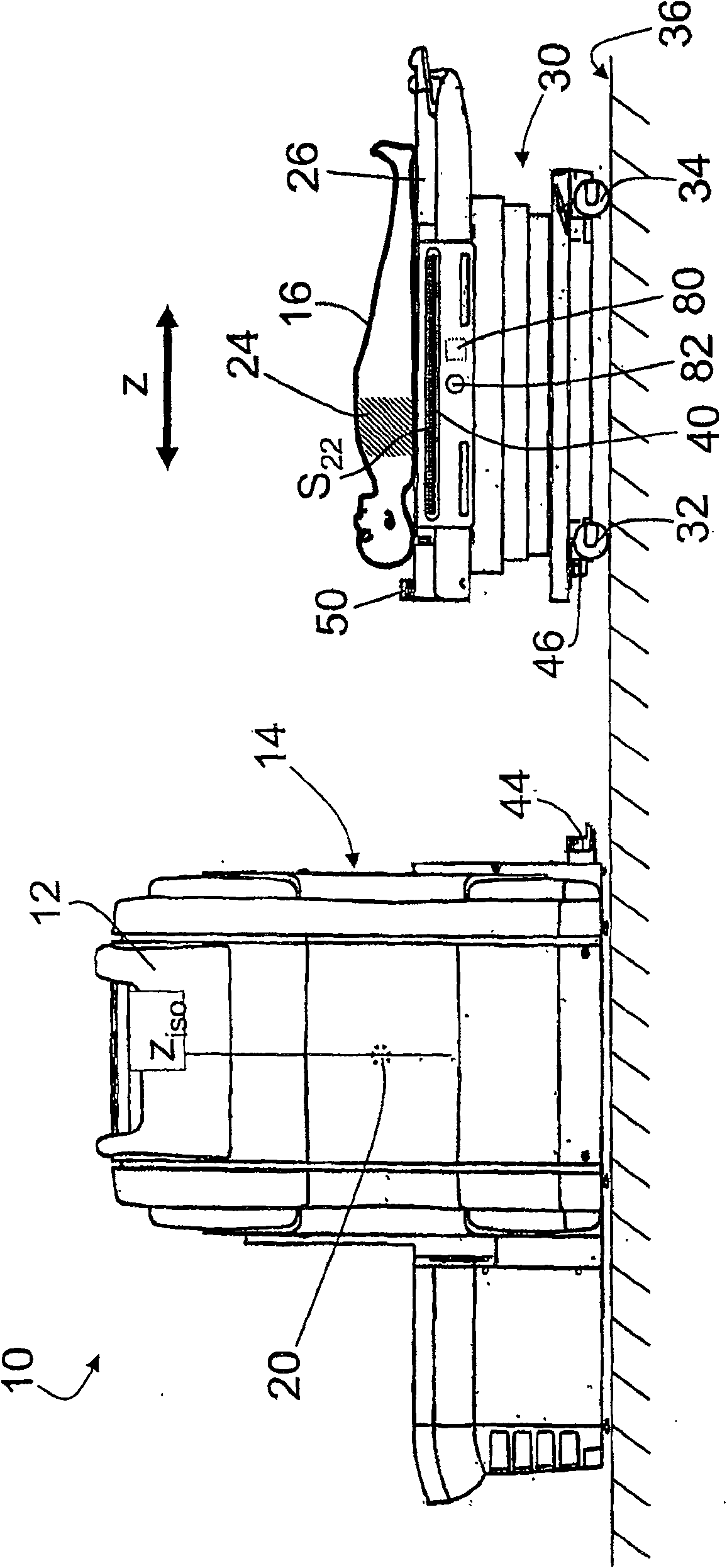
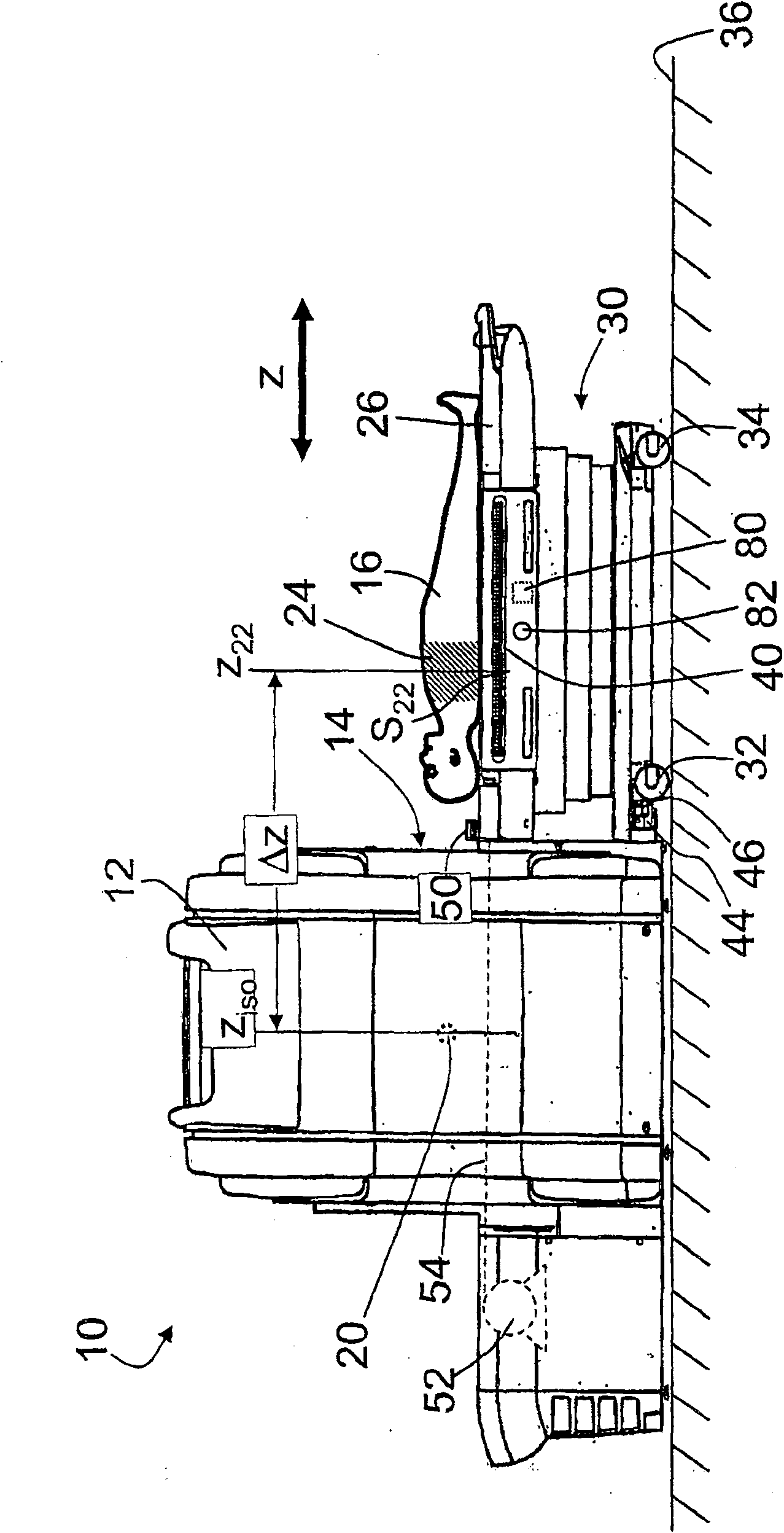
[0025] refer to figure 1 and figure 2 The magnetic resonance imaging scanner 10 includes a housing 12 that includes a plurality of components including at least a main magnet, magnetic field gradient coils, and one or more radio frequency coils (internal components not shown). Preferably, the main magnet is superconducting and cryoshrouded. Housing 12 defines a lumen 14 within which is placed an object to be imaged. Magnetic field gradient coils for spatially encoding magnetic resonance signals are housed in housing 12 or disposed within cavity 14, and one or more radio frequency coils and magnetic field gradient coils are used in conjunction to generate, shape and detect imaging objects. Other optional components of the resonant signal are also housed in the housing 12 or disposed within the inner cavity 14 .

[0026] In MRI, a patient 16 or other imaging subject is positioned within a lumen 14 of a main magnet, wherein the main magnet generates a static main magnetic fie...


PUM


Abstract

To position an imaging subject (16) in an imaging or therapy system (10), an imaging subject (16) is arranged on a linearly translatable tabletop (26) disposed on a movable trolley (30). A position ofa region of interest (24) of the imaging subject along the linearly translatable tabletop is selected using an elongated position selector (40, 40', 40'') that is elongated in a translation direction(z) of the linearly translatable tabletop (26). After the selecting, the movable trolley is docked with the imaging or therapy system (10). After the docking, the tabletop is linearly translated to move the imaging subject to the imaging or therapy system, the amount of linear translating being based on the selected position of a region of interest along the linearly translatable tabletop.

Description

technical field [0001] The following relates to medical imaging techniques. It has particular application in Magnetic Resonance Imaging (MRI), and will be described with specific reference to Magnetic Resonance Imaging. However, it also has applications in magnetic resonance spectroscopy, positron emission tomography (PET) imaging, single photon emission computed tomography (SPECT) imaging, computed tomography (CT) imaging, radiation therapy, and other imaging and treatment modalities, Therein, a patient or other imaging subject is aligned with the imaging or treatment system. Background technique [0002] Medical imaging or treatment is typically directed to a region of interest, such as the heart, lungs, brain, arms, legs, torso, or sometimes the entire body. For radiation therapy, the cancerous organ is typically targeted. Typically, an MRI scanner or other medical device used to perform imaging or therapy is stationary and images or otherwise operates on a fixed volum...

Claims


Application Information

Patent Timeline
Patent Type & Authority Patents(China)
IPC IPC(8): A61B5/055A61B6/04
CPCA61B5/0555A61B6/469A61B6/0407A61B5/704A61B6/04A61B5/055
Inventor P·T·坎普森B·W·佩托特
Owner KONINK PHILIPS ELECTRONICS NV
Why Eureka
Try Eureka