Welding process of section steel structure

A welding process and profile technology, applied in welding equipment, auxiliary welding equipment, welding/cutting auxiliary equipment, etc., can solve problems such as affecting production efficiency, hidden dangers of workpiece safety, affecting welding seam quality, etc., to reduce welding auxiliary time, overall Small deformation, the effect of ensuring the quality of the weld

Active Publication Date: 2010-03-03
CRRC TANGSHAN CO LTD
View PDF6 Cites 0 Cited by
  • Summary
  • Abstract
  • Description
  • Claims
  • Application Information

AI Technical Summary

Problems solved by technology

However, this traditional assembly method has exposed many shortcomings in actual production: first, in the process of welding the first side with the slot structure, the welding deformation of the workpiece leads to the welding of the second side without the slot structure When the edge is wrong and the groove shrinks, the groove is not easy to penetrate, which seriously affects the quality of the weld and causes hidden dangers to the safety of the workpiece; second, in order to control the edge error during the welding process, the groove must be cleaned after assembly Intensive spot welding, and before welding each weld, the spot weld must be cleaned for formal welding. Too many spot welds make welding auxiliary processes such as spot welding and cleaning spot welds a waste of time. A lot of time greatly affects the production efficiency; third, although the traditional assembly method ensures the convex shape of the workpiece after welding, due to the excessive welding deformation, the workpiece is convex too much, far exceeding the tolerance of the flatness of the workpiece. Coupled with the constraints of the slot structure on the convex side, it is very difficult to adjust and repair
To sum up, from the comprehensive analysis of weld quality, production efficiency and welding deformation, the traditional method of frontal assembly is not suitable for the assembly and welding of front slot structural profiles.

Method used


Image

  • Welding process of section steel structure
  • Welding process of section steel structure
  • Welding process of section steel structure

Examples


Embodiment Construction

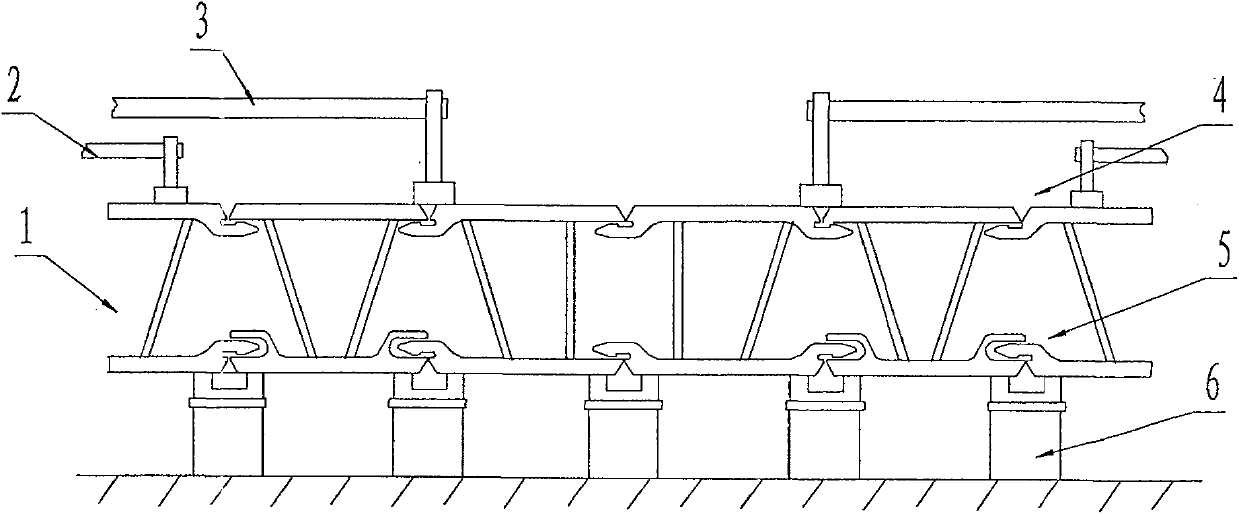
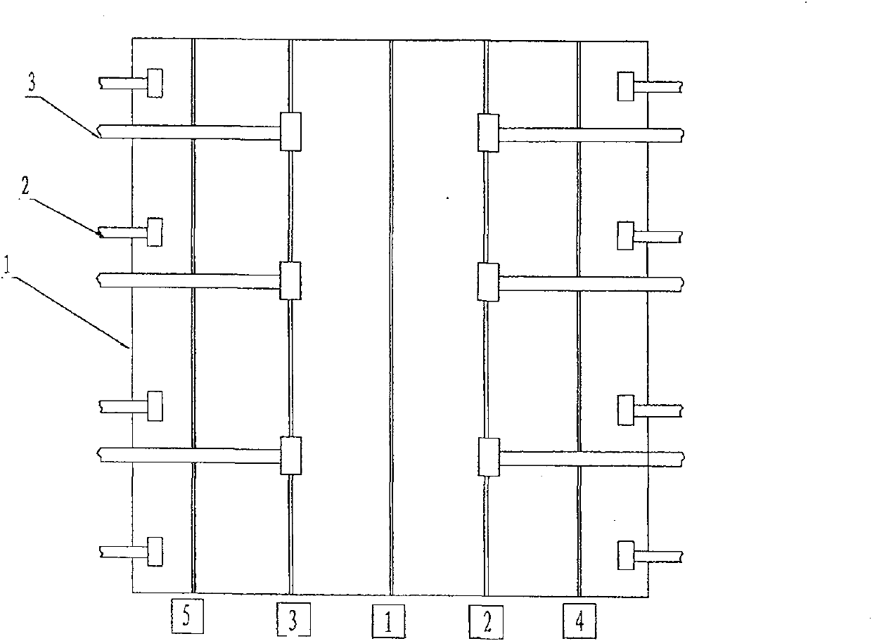
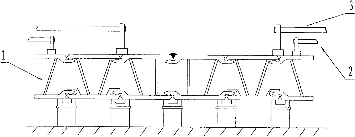
[0026] The method of the present invention is aimed at the profile with backing plate slot structure on the groove, and provides a welding process method of first welding the groove without backing plate slot on the back side, and then welding the front side with backing plate slot structure groove. The method combines clamp pressure The clamping and pressing iron compression method provides the welding sequence of each weld seam, so that it can better control the pre-weld misalignment and post-weld deformation of large-sized profile workpieces, and can reduce the difficulty of post-weld repairs. The method of the present invention will be further described in detail below in conjunction with a specific embodiment, which is a welding process for assembling large-size aluminum profiles for rail passenger car bodies using the method.

[0027] see figure 1 , figure 2 In the first step of welding, the workpiece 1 is reversed, that is, the side of the profile without the backing...


PUM

PropertyMeasurementUnit
lengthaaaaaaaaaa

Abstract

A technological method for welding a sectional material structure belongs to the welding technical field, and is used for solving the problems that the dislocation of forward erection welding procedure for large-sized sectional material is not easy to control, and too much spot welding for welding lines is needed. The technical proposal comprises the steps of reverse assembly of a workpiece, reverse welding, forward assembly of the workpiece, forward welding, etc. The invention adopts the technological method of first reverse assembly and then forward assembly during welding the large-sized section material, thereby bringing into full play the advantage that a slot structure restricts the dislocation of a divided edge, preventing the deformation produced by the welding of a first surface from causing the dislocation and shrinking of the divided edge of a second surface, and ensuring the quality of the welding line of the second surface; in addition, since the divided edge of the secondsurface can be directly welded without the need of assembly and adjustment, only a small amount of spot welding is performed before the welding line of the second surface is welded, thus greatly reducing the time of welding assistance; furthermore, the method, combined with a proper welding order and preset predeformation treatment before welding, can ensure that the amount of overall deformationof the workpiece after welding is small, and that the requirement for final planeness can be satisfied simply through simple correction.

Description

technical field [0001] The invention relates to a welding process method for a large-size profile structure, which belongs to the field of welding technology. Background technique [0002] Butt groove welding is a common welding connection method for profiles. At present, there are two types of groove designs for butt joints used at home and abroad, that is, the structure of the groove backing plate without slots and the structure with slots. see Figure 9 , the groove backing plate has no slot structure. One profile has only the bevel slope, and the other profile groove has its own backing plate. And form the welding groove. Due to the tolerance of the size of the profiles and the flatness of the tooling pads in this structure, after the profiles are assembled, there will be a certain difference in the height of the profiles on both sides of the groove, that is, the wrong edge before welding. The wrong side generally appears at the groove of the second side of the profil...

Claims


Application Information

Patent Timeline
Patent Type & Authority Patents(China)
IPC IPC(8): B23K33/00B23K37/053
Inventor 刘志平胡文浩王秀义
Owner CRRC TANGSHAN CO LTD
Why Eureka
Try Eureka