

Dehumidifying air conditioning system
A technology for air conditioning systems and dehumidifiers, which is applied in air conditioning systems, air treatment details, space heating and ventilation, etc., and can solve problems such as changes, changes in dehumidification performance of supply air, and large-scale dehumidification systems.
- Summary
- Abstract
- Description
- Claims
- Application Information
AI Technical Summary
Problems solved by technology
Method used
Image

Examples
Embodiment 2
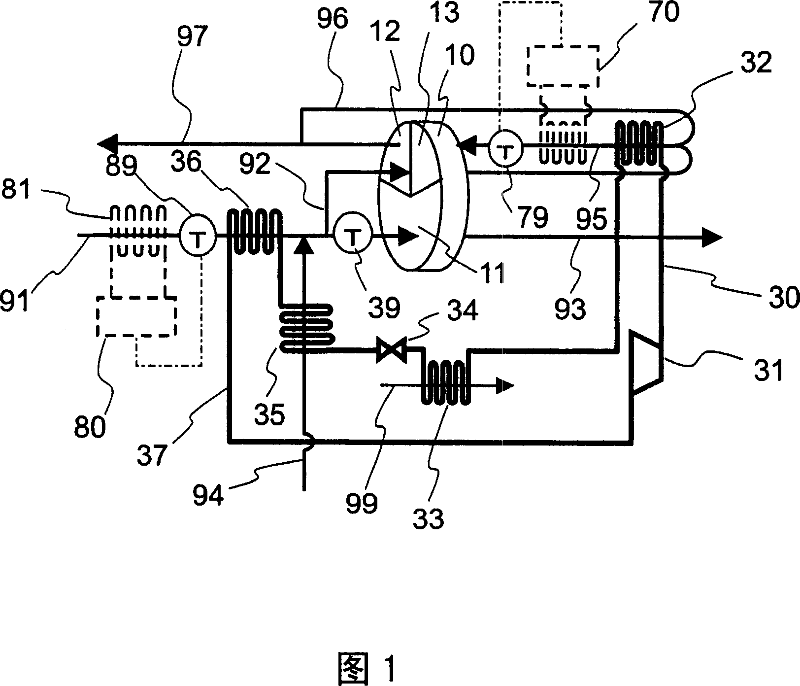
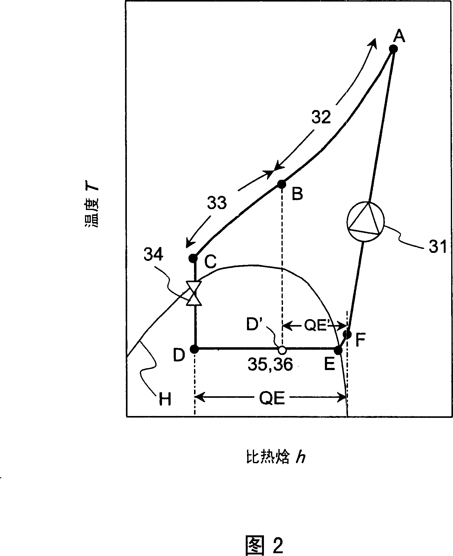
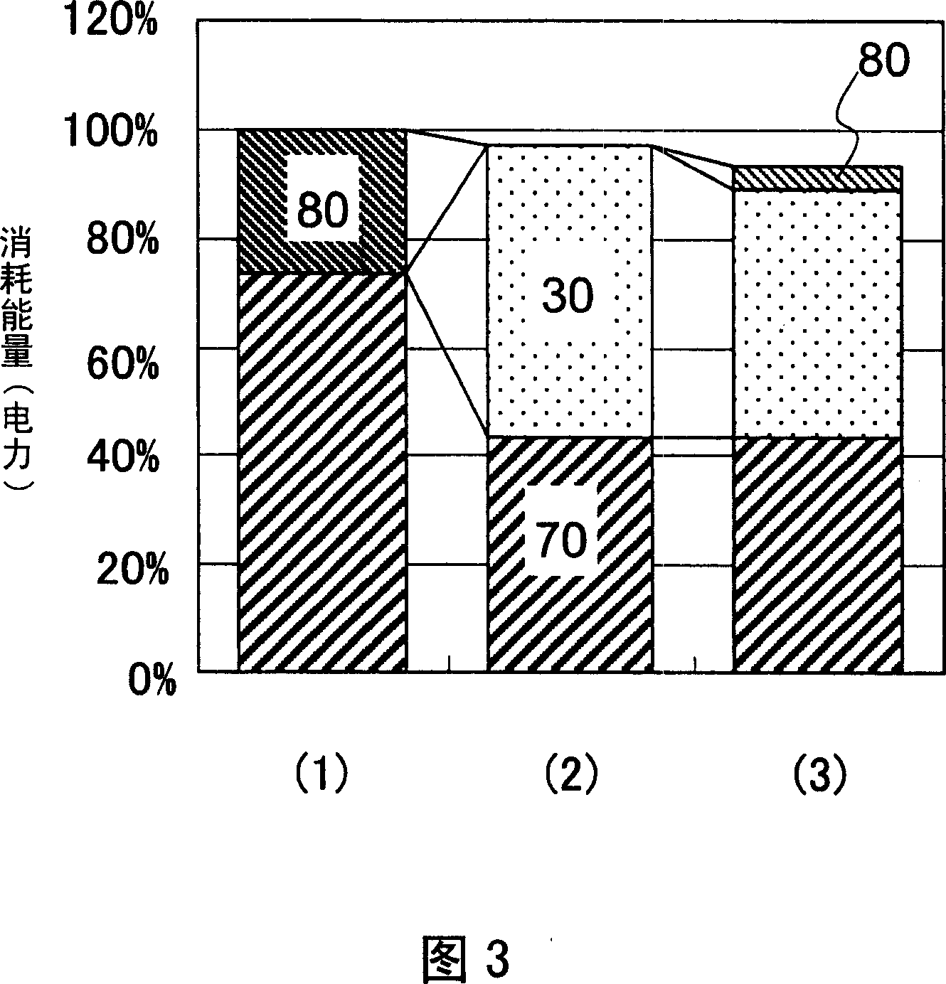
[0062] Next, another embodiment of the present invention will be described with reference to FIGS. 4 to 7 . FIG. 4 is an overall system diagram of the dehumidification and air conditioning system according to the present embodiment, and FIG. 5 is a diagram showing the heat pump cycle used in the present embodiment on a temperature-enthalpy diagram. 6 is a graph showing the relationship between the temperature efficiency of the internal heat exchanger used in the present example and the power consumption and the like of the dehumidifying air-conditioning system according to the present example. FIG. 7 is a graph comparing the energy consumption of the dehumidifying and air-conditioning system according to the present embodiment and the details thereof with the three systems in FIG. 3 . In the respective figures, the same reference numerals as those in FIG. 1 are attached to the same components as those in the embodiment of FIG. 1 . In addition, in the following description, it...
Embodiment 3
[0080]The third embodiment will be described using FIGS. 8 to 12 . FIG. 8 is an overall system diagram of the dehumidification and air conditioning system according to the present embodiment. FIG. 9 is a diagram showing the heat pump cycle used in this example on a temperature-enthalpy diagram. FIG. 10 is a diagram showing the cell structure of the present embodiment. In addition, FIG. 11 is a detailed diagram comparing the energy consumption in the summer peak condition of the dehumidifying air-conditioning system according to the present Example and the details thereof with the case of using the heat pump. In addition, FIG. 12 is a graph comparing the monthly average energy consumption according to the present Example with the case where the heat pump is not used like FIG. 10 .
[0081] In FIG. 8 , the difference from FIG. 1 is that an on-off valve 83 is provided on the direct expansion cooling coil (first cooling coil) 81 which is the output of the refrigerator 80 to cool...
Embodiment 4
[0108] Next, a fourth embodiment of the present invention will be described with reference to FIG. 13 . The dehumidification and air-conditioning system of FIG. 13 has substantially the same configuration as that of FIG. 8, but differs in the following points. In the embodiment of FIG. 8 , the indoor return air 94 recirculated from the room is cooled by the second cooling coil 82 . In contrast, in the present embodiment, the second cooling coil 82 is used to cool the indoor air 94 . The process air in which the return air 94 and the outside air 91 introduced from the outside have merged is cooled.
[0109] In the present embodiment, the process air before flowing into the process area 11 of the dehumidification rotor 10 is cooled by the second cooling coil 82 . As a result, compared with the third embodiment, the rotor inlet air temperature detected by the temperature sensor 39 can be stably controlled to be close to the target value by the capacity control of the refrigerato...
PUM
 Abstract
Description
Claims
Application Information