
Method for sticking metallic thin sheet to frame, and device therefor

A metal sheet and framing technology, applied in lighting devices, metal material coating process, ion implantation plating, etc., can solve the problems of deformation or relaxation of the opening, easy deformation, and inability to obtain a slit pattern, so as to prevent deformation. Effect

Active Publication Date: 2007-07-18
DAI NIPPON PRINTING CO LTD
View PDF2 Cites 25 Cited by
  • Summary
  • Abstract
  • Description
  • Claims
  • Application Information

AI Technical Summary

Problems solved by technology

[0005] However, in the multi-faceted mask device described in Patent Document 2, when the multi-faceted mask is thin and easily deformed, there is a problem that deformation or looseness occurs in the opening, and a desired slit pattern cannot be obtained.
In addition, in this multi-face mask device, since it is a structure in which winding shafts are respectively provided on the four sides of the frame to roll up the mounting parts 5 on the four sides of the multi-face mask 1A, the structure is complicated and the cost becomes high. question

Method used


Image

  • Method for sticking metallic thin sheet to frame, and device therefor
  • Method for sticking metallic thin sheet to frame, and device therefor
  • Method for sticking metallic thin sheet to frame, and device therefor

Examples


no. 1 Embodiment approach

[0064] The present invention can be applied to any metal thin plate that needs to be kept in a flat state without deformation or slack, but it is preferably used as a multi-faceted mask for vapor deposition (having a plurality of mask parts) for the manufacture of organic EL elements that require precision. sheet metal used for masks). Hereinafter, preferred embodiments of the present invention will be described by taking a thin metal plate used as an example of a multi-faceted mask for vapor deposition in the production of an organic EL element.

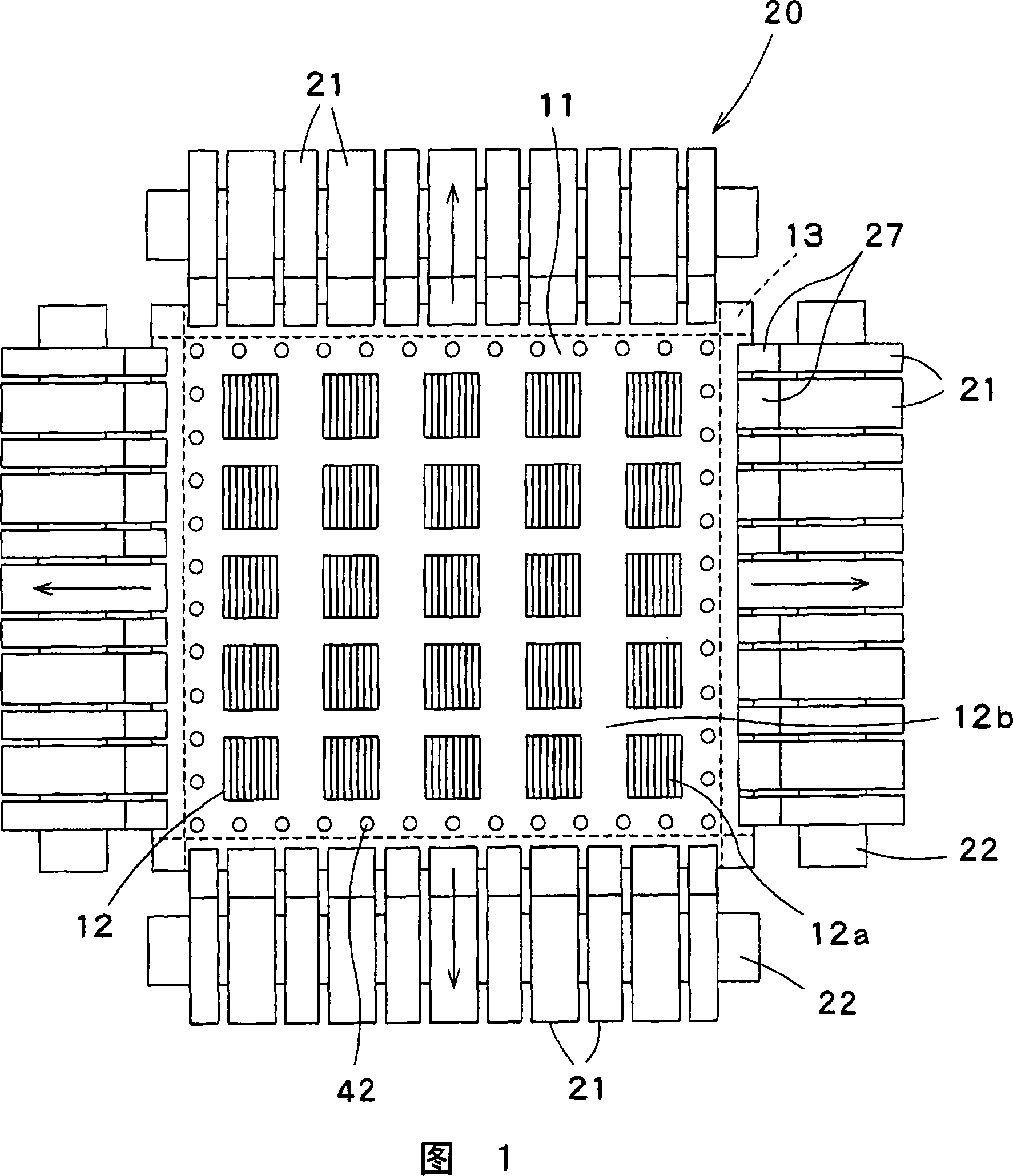
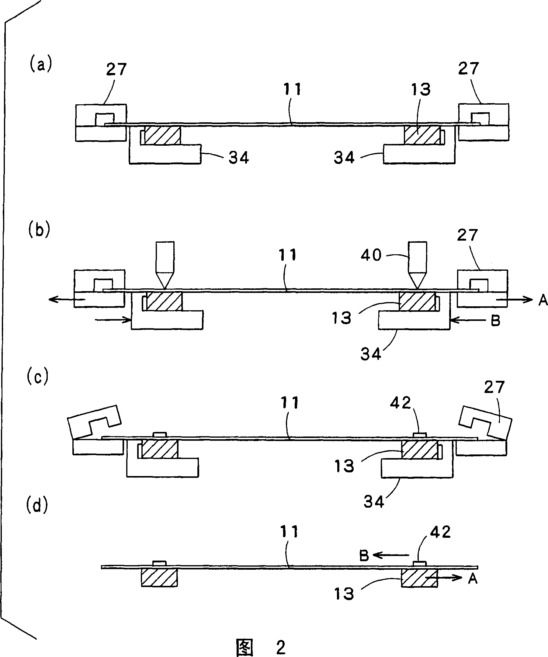
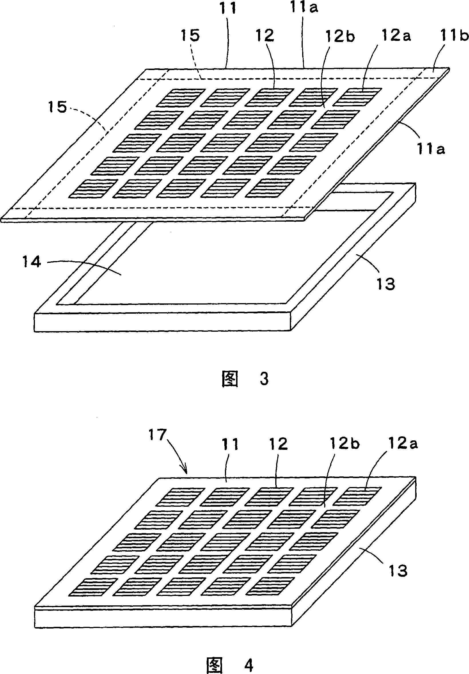
[0065] Fig. 1 is a schematic plan view of a framing device for a thin metal plate according to an embodiment of the present invention, Fig. 2 is a schematic cross-sectional view showing the sequence of framing operations performed by the framing device, and Fig. 3 is a schematic sectional view showing the metal sheet processed by the framing device. A schematic perspective view of the thin plate and the frame, Fig. 4 is a schematic ...

no. 2 Embodiment approach

[0092] The present invention can be applied to the case where an arbitrary rectangular metal mask (also referred to as a metal sheet) that needs to be kept in a flat state without deformation and slack is mounted on a rectangular frame-shaped frame (also referred to as a frame), but is preferably applied as A metal mask used for vapor deposition multi-faceted masks for the manufacture of organic EL elements that require high precision. Hereinafter, preferred embodiments of the present invention will be described by taking, as an example, a metal mask used as a multi-faceted mask for vapor deposition in the production of an organic EL element.

[0093] FIG. 20 is a schematic perspective view showing a metal mask and a frame-shaped frame processed by a frame mounting device (also called a thin metal plate frame mounting device) according to an embodiment described later, and FIG. A schematic perspective view of the formed mask assembly.

[0094] In FIG. 20 , 101 is a rectangula...


PUM


Abstract

Each side (11a) of a thin metal plate (11) is held with clamps (27). The thin metal plate (11) is pulled by the clamps (27), and tensile force by each clamp is adjusted to hold the thin metal plate (11) in a flat state without distortion and sagging. At the same time, a frame (13) is elastically deformed by pressing it, with a force having the same magnitude as the tensile force applied to the thin metal plate (11), in the opposite direction to the tensile force. Then, in this state the thin metal plate (11) is welded and fixed to the frame (13) by a spot welding machine (40). When the thin metal plate (11) and the frame (13) are freed, tensile force remaining in the plate (11) is cancelled by restoring force of the frame (13). This prevents the frame (13) from being pulled by the thin metal plate (11) and deformed, and the frame (13) can hold the thin metal plate (11) in a state without distortion and sagging.

Description

technical field [0001] The present invention relates to a method and apparatus for fixing a thin metal plate, such as a metal plate including a plurality of slits used as a vapor deposition mask used in a manufacturing process of an organic EL element, to a frame in a flat state without deformation. Like a thin metal plate at the opening, it is thin and has regions with different rigidities. Background technique [0002] Conventionally, vacuum vapor deposition is performed in the manufacture of organic EL elements, and a metal plate having an opening including a plurality of slits is used as the vapor deposition mask. In addition, during vapor deposition, this vapor deposition mask is attached to a rigid frame having an opening larger than the above-mentioned opening through a magnet or the like. However, in recent years, the miniaturization of the layout has been progressing. If the slits formed in the openings become finer and the thickness of the deposition mask itself b...

Claims


Application Information

Patent Timeline
IPC IPC(8): C23C14/04H05B33/10H05B33/14
Inventor 土屋辉直下村贵一矢口孝
Owner DAI NIPPON PRINTING CO LTD
Learn More