
Method and its device for detecting high energy semiconductor laser divergence angle

A test method and laser technology, which is applied in the direction of semiconductor laser, single semiconductor device test, optical instrument test, etc., can solve the problems of CCD and detector saturation, affect the measurement accuracy, change the shape of the light spot, etc., and achieve easy production and assembly, structure Simple, low-cost effect

Inactive Publication Date: 2007-07-25
DALIAN MARITIME UNIVERSITY
View PDF0 Cites 27 Cited by
  • Summary
  • Abstract
  • Description
  • Claims
  • Application Information

AI Technical Summary

Problems solved by technology

However, when these methods are used to measure high-power lasers, there are the following problems: first, the surface emission of high-energy area array lasers is directly used as a point light source in the existing test methods, which will cause test errors; second, if the existing test methods are used The direct detection of the test method will saturate or burn the CCD and the detector. Attenuation first and then detection will change the shape of the spot, which will seriously affect the accuracy of the measurement.

Method used


Image

  • Method and its device for detecting high energy semiconductor laser divergence angle
  • Method and its device for detecting high energy semiconductor laser divergence angle
  • Method and its device for detecting high energy semiconductor laser divergence angle

Examples


Embodiment Construction

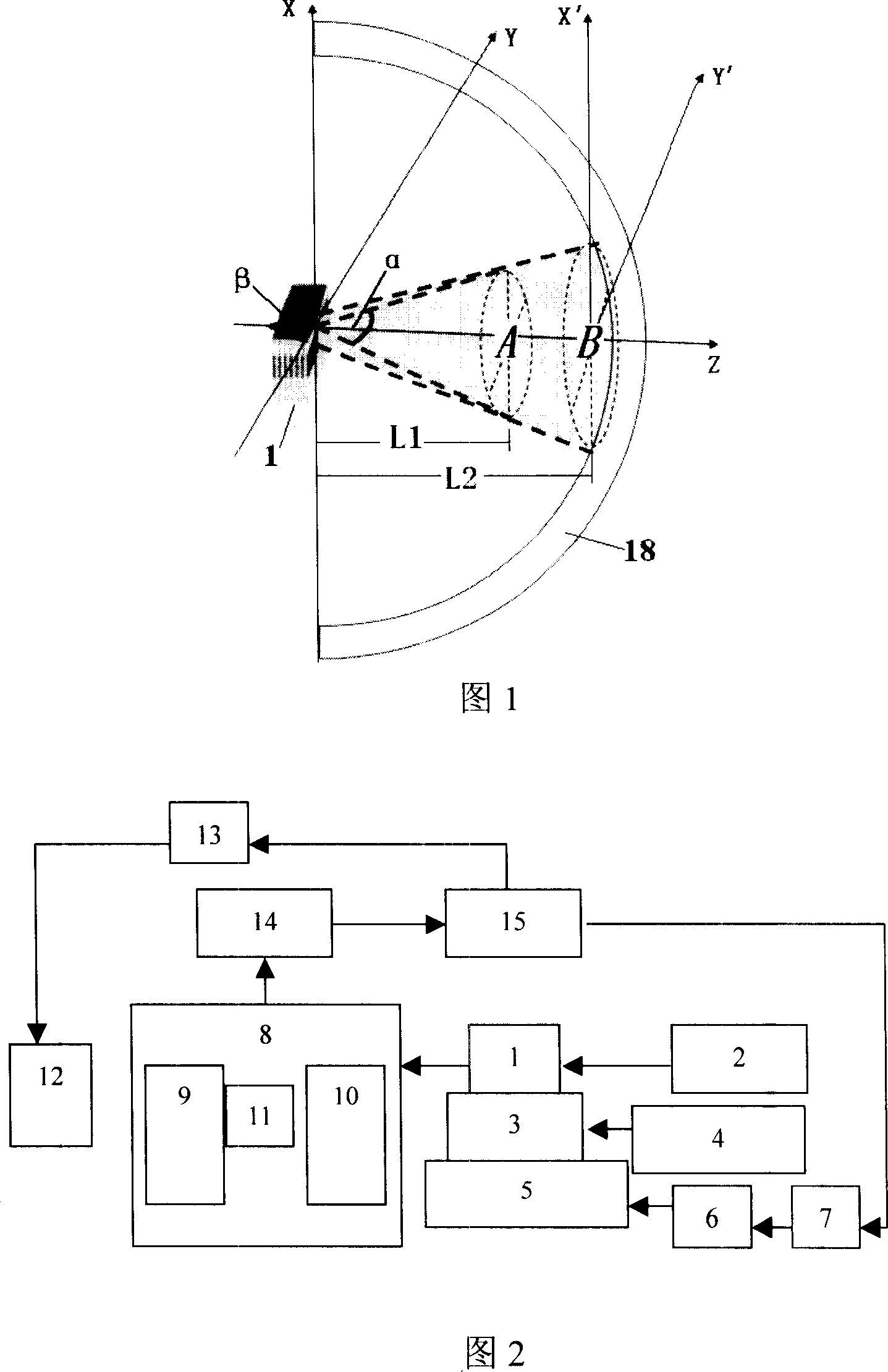
[0050] Figure 1 shows the basic testing principle of the present invention. In the previous divergence angle testing methods, the laser is usually equivalent to a point light source. Therefore, only one spot at a certain distance from the laser, such as the spot A at the distance L1 in Figure 1, can be used to calculate the laser's Divergence angle, the divergence angle obtained in this way is α in Figure 1. The invention calculates the divergence angle of the laser on the basis of the geometrical characteristics of the outer edge curves of two light spots where the laser beam is transmitted to different distances. As shown in Figure 1, the divergence angle is calculated based on the spot A and spot B at two distances from the lasers L1 and L2, and the angle can be expressed as β in the figure. Obviously, compared with α, β takes into account the influence of the size of the light-emitting surface of the laser itself on the divergence angle, and can more accurately represent ...


PUM


Abstract

Using geometric characteristics of outer margin curves of two light spots at different distances along direction of beam transmission, the disclosed method obtains divergence angle of laser. Through rotational scanning detection, concentric placed two light detectors perpendicular to each other obtain outer margin curves. Multiple optical fibers are distributed on the said light detector evenly. The disclosed device is composed of drive power supply, cooling water platform, cooling water circulation system, 4D traveling platform, electrical motor set, drive, data acquisition module, and PC etc. The light-receiving module includes light detectors. The light-receiving module, data acquisition module, and PC are connected electrically. The invention solves issue of test error caused by regarding face radiation of area array laser as spot light source so as to avoid damaging and burning detector caused by too large power of laser. Advantages are: accurate and reliable.

Description

technical field [0001] The invention relates to high-energy semiconductor laser beam quality detection. In more detail, it is a method for measuring the divergence angle of a high-energy semiconductor laser, and the present invention also relates to a device used to realize the above method. Background technique [0002] The beam divergence angle of a high-energy semiconductor laser is an important index to characterize the laser beam quality. The accurate measurement of the beam divergence angle is the key to the design of its collimation system and its application. At present, in the measurement of the beam divergence angle of semiconductor lasers, the CCD camera measurement method and the cantilever beam detector scanning method are commonly used. However, when these methods are used to measure high-power lasers, there are the following problems: first, the surface emission of high-energy area array lasers is directly used as a point light source in the existing test met...

Claims


Application Information

Patent Timeline
Patent Type & Authority Applications(China)
IPC IPC(8): H01S5/00H01S3/00G01M11/00G01M11/02G01R31/26
Inventor 董丽丽
Owner DALIAN MARITIME UNIVERSITY
Learn More