Fault detection instrument of rotary equipment based on acoustic emission technique

An acoustic emission technology and rotating equipment technology, applied in the field of rotating equipment fault detectors, can solve problems such as simple functions, lack of real-time detection and analysis of collected signals, and difficulty in real-time detection

Inactive Publication Date: 2007-08-01
天津航天长征技术装备有限公司
View PDF1 Cites 22 Cited by
  • Summary
  • Abstract
  • Description
  • Claims
  • Application Information

AI Technical Summary

Problems solved by technology

Existing fault detectors for rotating equipment use vibration sensors (acceleration, speed or displacement sensors) to pick up equipment vibration signals and use single-chip microcomputer technology for signal processing. The low-frequency disturbance signal will be picked up by the acceleration sensor, which will affect the test results and lead to misjudgment. Moreover, the vibration analysis method judges the fault through the analysis and processing of acceleration, displacement and other signals, which is equivalent to secondary signal processing. real-time detection; single-chip microcomputer-based data analysis and processing system has slow operation speed, low precision, relatively simple functions, and does not meet the requirements for real-time detection and analysis of collected signals

Method used


Image

  • Fault detection instrument of rotary equipment based on acoustic emission technique
  • Fault detection instrument of rotary equipment based on acoustic emission technique
  • Fault detection instrument of rotary equipment based on acoustic emission technique

Examples


Embodiment Construction

[0023] The present invention will be described in further detail below in conjunction with the accompanying drawings.

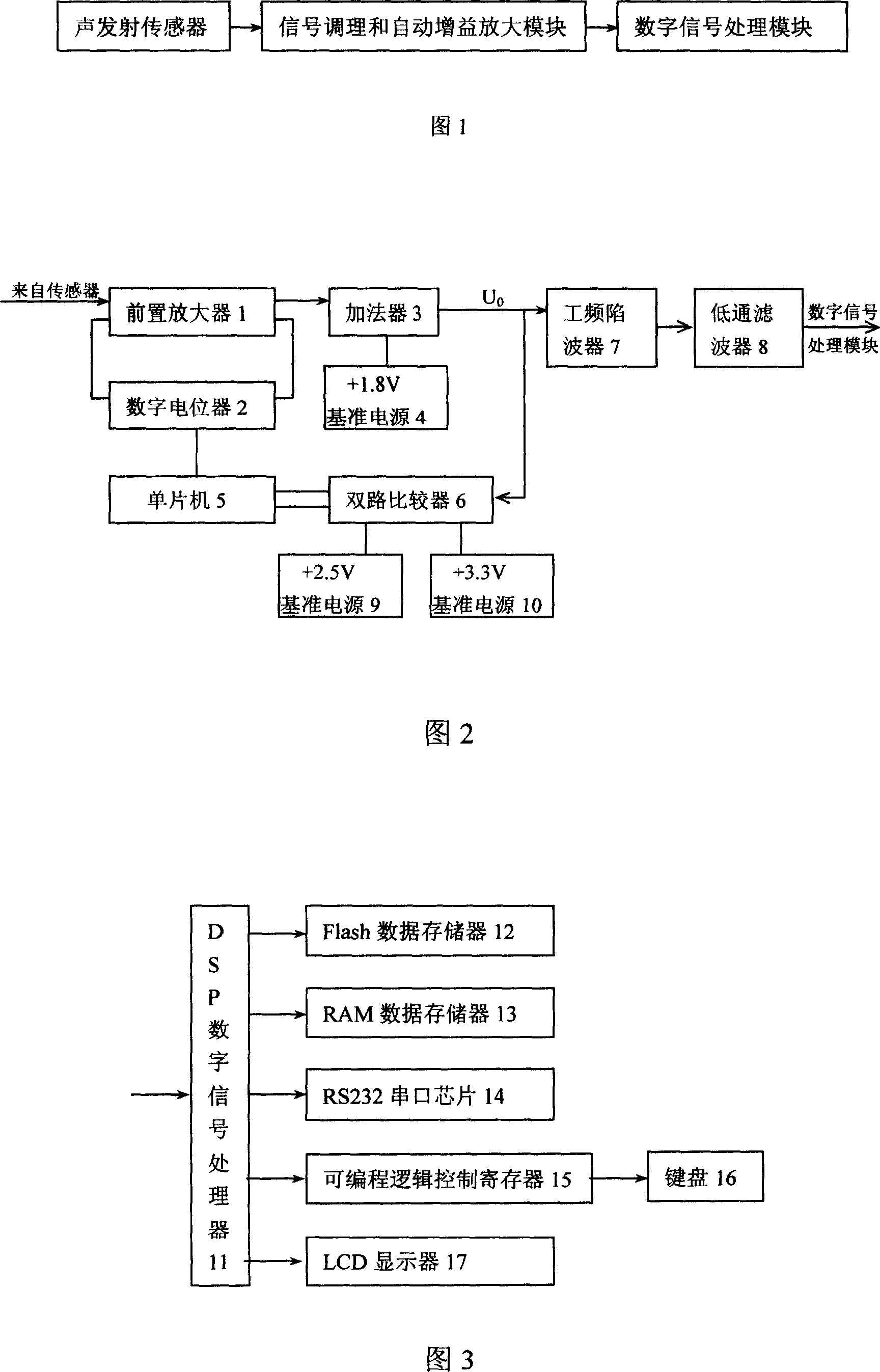
[0024] As shown in Figure 1, the rotating equipment fault detector consists of three parts: an acoustic emission sensor, a signal conditioning and automatic gain amplification module, and a digital signal processing module. The acoustic emission sensor detects the acoustic emission signal of the rotating equipment; the signal conditioning and automatic gain The amplification module realizes the pre-amplification, automatic gain control, power frequency notch, low-pass filtering and other functions of the output signal of the acoustic emission sensor, so that the high input impedance of the acoustic emission sensor becomes a low output impedance and amplifies the weak electrical signal, filters In addition to interference signals and useless signals, the voltage of the detection signal after signal conditioning and automatic gain amplification is controlled bet...


PUM


Abstract

This invention relates to one rotation device fault test machine based on sound emission technique, which comprises sound emission sensor, signal adjust and automatic gain amplifier module and digital signal process module, wherein, the digital signal process module comprises DSP digital signal processor, Flash data memory, RAM data memory, RS232 series chip, programmable logic controller, keyboard, and LCD display.

Description

technical field [0001] The invention relates to a rotating equipment fault detector, in particular to a device fault detector based on acoustic emission technology. Background technique [0002] The rotating equipment fault detector can be used to detect the running state of the rotating equipment, which has obvious economic and social benefits for ensuring the safe operation of the rotating equipment and avoiding major equipment accidents and process accidents. Existing fault detectors for rotating equipment use vibration sensors (acceleration, speed or displacement sensors) to pick up equipment vibration signals and use single-chip microcomputer technology for signal processing. The low-frequency disturbance signal will be picked up by the acceleration sensor, which will affect the test results and lead to misjudgment. Moreover, the vibration analysis method judges the fault through the analysis and processing of acceleration, displacement and other signals, which is equiv...

Claims


Application Information

Patent Timeline
Patent Type & Authority Applications(China)
IPC IPC(8): G01M19/00G01H11/08G01M99/00
Inventor 吴斌王庆锋何存富宋国荣宋吟蔚
Owner 天津航天长征技术装备有限公司
Why Eureka
Try Eureka