

Dynamic fluidization atmosphere furnace
A fluidized gas and dynamic technology, applied in fluidized bed furnaces, furnaces, furnace types, etc., to achieve the effect of increasing furnace maintenance, reducing operating costs, and reducing collision damage between particles
- Summary
- Abstract
- Description
- Claims
- Application Information
AI Technical Summary
Problems solved by technology
Method used
Image

Examples
Embodiment 1
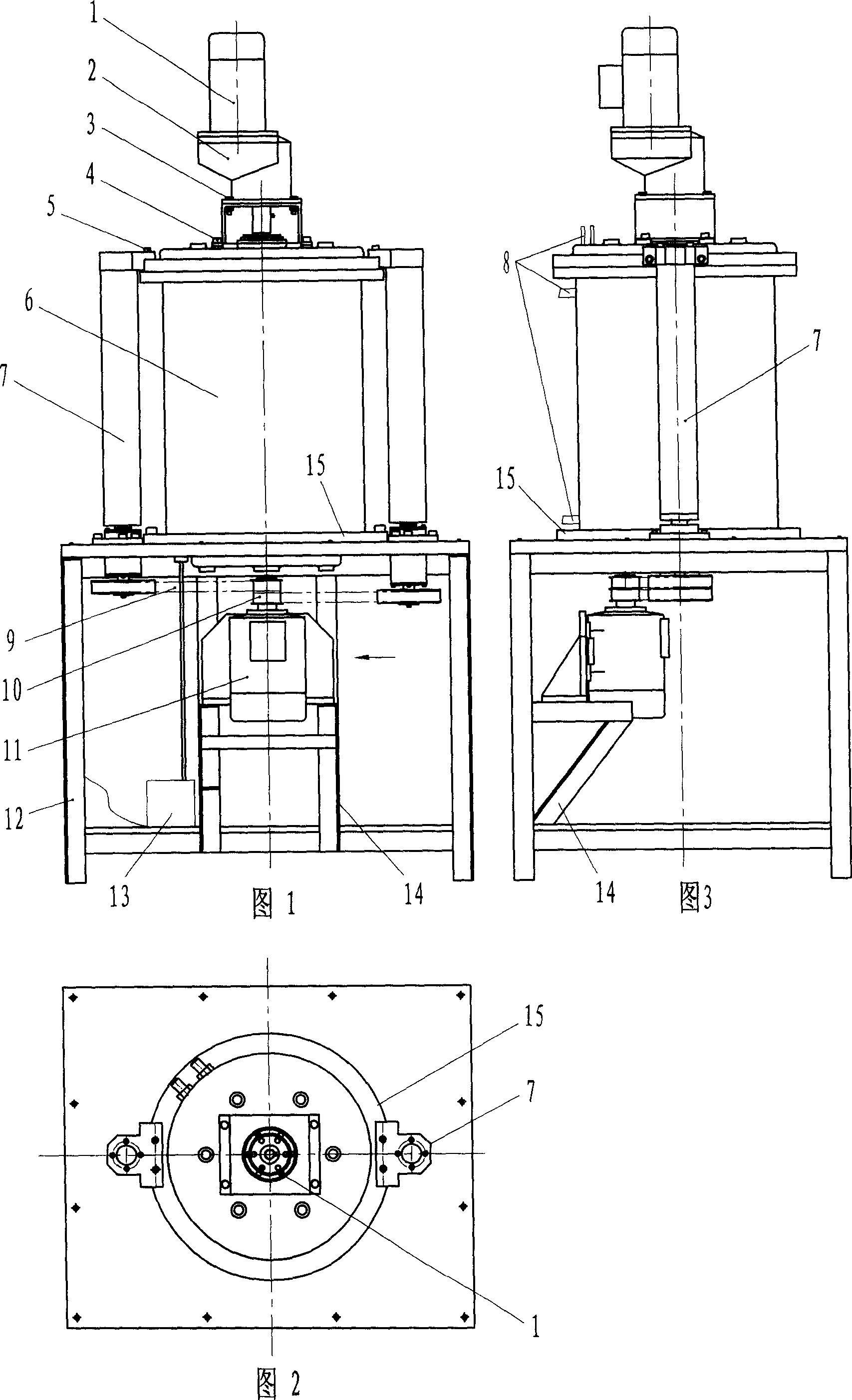
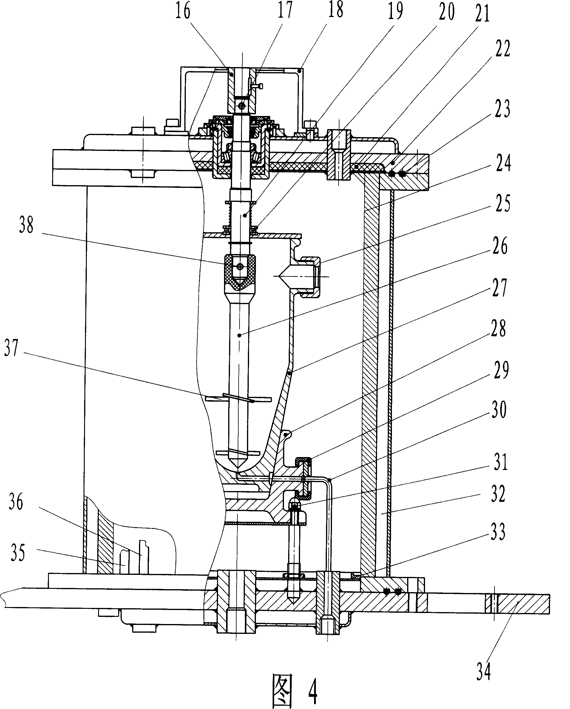
[0026] Example 1: The nanoparticles to be reduced are loaded into the container, the reactor is fixed on the base of the furnace body and the gas nozzle is rotated to connect with the gas path, the furnace cover is closed by the lifting motor, and the propeller stirring rod is lowered at the same time. Put into the holding container and cover the top of the holding container. Lock the furnace cover, open the circulating cooling water valve, open the gas valve, set the stirring speed, heating process, and reaction parameters on the programmable touch LCD display of the operation and circuit control device, and set the gas flow on the gas circuit control device. The flow rate, the mixing ratio of the reducing gas, and the start-up procedure automatically complete the reduction process. The excess reducing atmosphere and the water vapor generated by the reaction are discharged through the exhaust device and combustible gases such as hydrogen are burned. During this period, observ...
Embodiment 2
[0027] Embodiment 2: The nanoparticles to be denucleated are loaded into the container, the container is fixed on the base of the furnace body and the gas nozzle is rotated to connect with the gas path, the furnace cover is closed by the lifting motor, and the propeller stirs at the same time The rod is lowered into the reactor and the cap is placed over the top of the reactor. Lock the furnace cover, open the circulating cooling water valve, open the gas valve, set the stirring speed, heating process, and reaction parameters on the programmable touch LCD display of the operation and circuit control device, and set the gas flow on the gas circuit control device. The flow rate, gas mixing ratio, and start-up procedure automatically complete the organic nuclear cracking process, and the excess atmosphere and cracking steam produced by the reaction are discharged through the exhaust device. During this period, observe the dynamic fluidization state of nanoparticles through the ob...
Embodiment 3
[0028]Embodiment 3: The nano-particles to be denucleated and reduced are loaded into the container, the container is fixed on the base of the furnace body and the gas nozzle is rotated to connect with the gas path, the furnace cover is closed by the lifting motor, and at the same time The propeller stirring rod is lowered into the reactor, and the cap covers the top of the reactor. Lock the furnace cover, open the circulating cooling water valve, open the gas valve, set the stirring speed, heating process, and reaction parameters on the programmable touch LCD display of the operation and circuit control device, and set the gas flow on the gas circuit control device. The flow rate, gas mixing ratio, and start-up procedure automatically complete the organic nuclear cracking treatment and reduction process. The excess atmosphere and cracking steam produced by the reaction are discharged through the ignition device and combustible gas is burned. During this period, observe the dyn...
PUM
 Abstract
Description
Claims
Application Information