Ratio control hydraulic pressure system for implementing belt steel rolling constant-tension control

A proportional control, hydraulic system technology, applied in tension/pressure control, fluid pressure actuating devices, etc., can solve the problems of high cost of coiling machinery and equipment, inability to meet short rolling pieces, complex control models, etc., to meet the requirements of a simple control system , Improve the availability and ensure the effect of cleanliness

Inactive Publication Date: 2007-08-08
NORTHEASTERN UNIV
View PDF0 Cites 27 Cited by
  • Summary
  • Abstract
  • Description
  • Claims
  • Application Information

AI Technical Summary

Problems solved by technology

This control method involves many links, and the control model is complex. It is an indirect control method with low control accuracy; the cost of uncoiling and coiling machinery a

Method used


Image

  • Ratio control hydraulic pressure system for implementing belt steel rolling constant-tension control
  • Ratio control hydraulic pressure system for implementing belt steel rolling constant-tension control
  • Ratio control hydraulic pressure system for implementing belt steel rolling constant-tension control

Examples


Embodiment 1

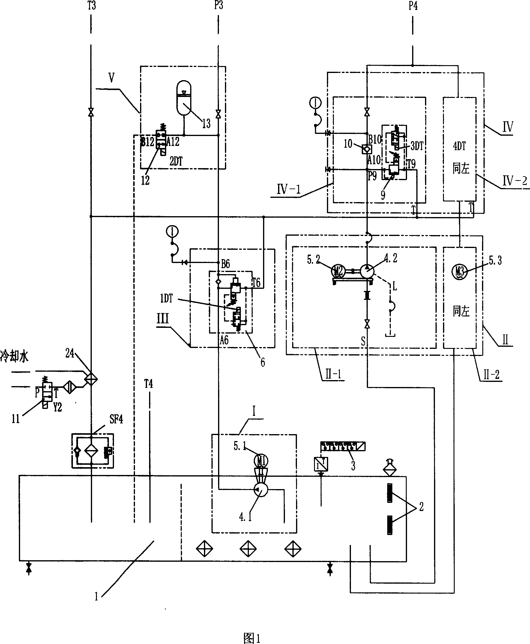
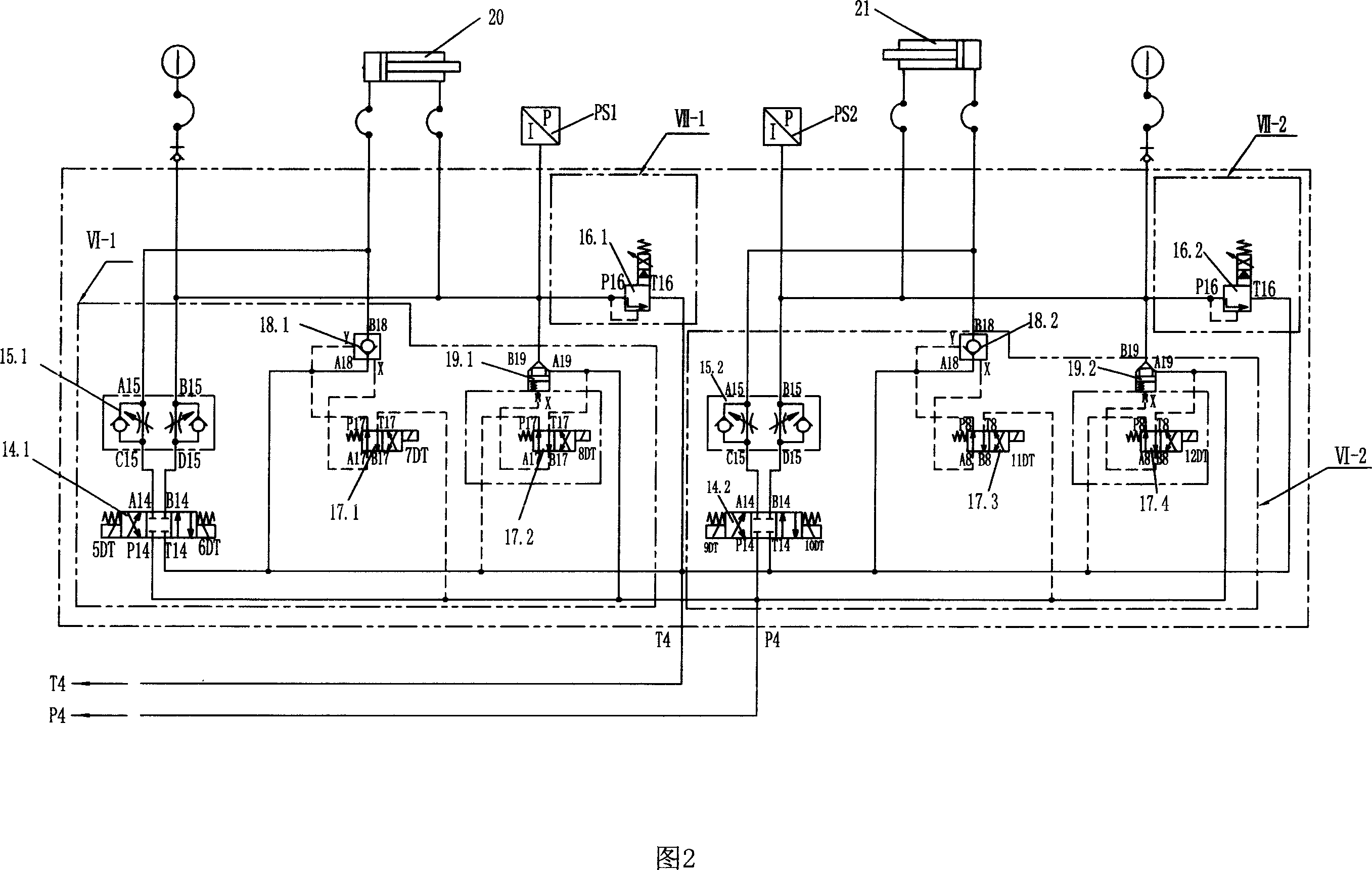
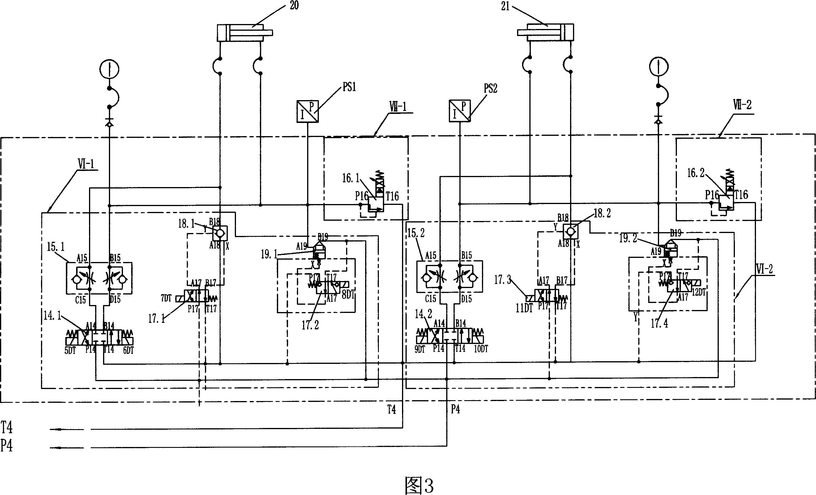
[0029] Embodiment 1: as shown in Figure 5, a single-stand four-high rolling mill is adopted, and a tension hydraulic cylinder 20 and 21 are respectively arranged before and after the rolling mill 26, and the rolled piece 27 is placed between the two work rolls 28 of the rolling mill 26, and on both sides of the rolled piece 27 One clamp hydraulic cylinder 7 and 8 are set respectively; diameter of backup roll 29: φ550 / φ500×450mm, diameter of work roll 28: φ150 / φ140×470mm; maximum rolling force: 2500kN, equipped with hydraulic AGC system; rolling speed: 0 ~0.1~0.24m / s; rolling tension range: 5~100kN; maximum stroke of hydraulic tension cylinder: 1500mm; minimum initial length of rolled piece: Lmin=500mm.

[0030] The basic configuration of the proportional control hydraulic system used to realize the constant tension control of strip rolling is as follows:

[0031] Hydraulic schematic diagrams are shown in Figure 1, Figure 2, and Figure 4: Low-pressure oil source: low-pressure p...

Embodiment 2

[0035] Embodiment 2: As shown in Figure 1, a single-stand four-high rolling mill is adopted, and a tension hydraulic cylinder 20 and 21 are respectively arranged before and after the rolling mill 26, and the rolled piece 27 is placed between the two work rolls 28 of the rolling mill 26, and on both sides of the rolled piece 27 One clamp hydraulic cylinder 7 and 8 are set respectively; diameter of backup roll 29: φ550 / φ500×450mm, diameter of work roll 28: φ150 / φ140×470mm; maximum rolling force: 2500kN, equipped with hydraulic AGC system; rolling speed: 0 ~0.1~0.24m / s; rolling tension range: 5~100kN; maximum stroke of hydraulic tension cylinder: 1500mm; minimum initial length of rolled piece: Lmin=500mm. The specifications of each valve, pressure sensor, and tension hydraulic cylinders 20, 21 are the same as those of Embodiment 1.

[0036] The high-pressure oil source, high-pressure safety pressure control device, proportional control device, and low-pressure oil source in the f...


PUM


Abstract

The proportional control hydraulic system with steel rolling constant tension control comprises tension hydraulic cylinder, pressure sensor, tension hydraulic cylinder control, hydraulic fixture, with the tension hydraulic cylinder control composed of high pressure oil source, high pressure safety pressure control, tension hydraulic action control and proportional control, with the high pressure oil source connecting with two tension hydraulic cylinder control device and proportional control, tension hydraulic action control device, proportional control device connecting with hydraulic cylinder bar free cavity and with bar cavity, the clamping control composed of low pressure oil source, low pressure control device, energy accumulation device, clamping cylinder action control, with the low pressure oil source connecting with two clamping hydraulic cylinder through low pressure control device, energy accumulation device and clamping cylinder action control device, tension hydraulic cylinder with bar cavity connected with pressure sensor, and each oil return opening and discharge opening connecting with the oil tank.

Description

technical field [0001] The invention belongs to the hydraulic control field of metallurgical mechanical equipment or experimental equipment, and is mainly used in cold rolling experimental rolling mills for the purposes of cold rolling product development, data optimization of cold rolling process, and process research and development of cold rolling product performance , a hydraulic proportional control system used to realize strip constant tension control. technical background [0002] The traditional single-stand reversing cold rolling mill realizes the strip tension control indirectly through the control of the uncoiler (and coiler) motor current. This method is usually based on the target value of strip tension and the current coil diameter, and fully considers the dynamic compensation torque caused by the acceleration and deceleration of the rolling mill and the static compensation torque used to compensate for bending and mechanical losses. Calculate the theoretical ...

Claims


Application Information

Patent Timeline
IPC IPC(8): B21B37/48F15B15/18
Inventor 张福波李建平刘相华王国栋毕勇邹杰
Owner NORTHEASTERN UNIV
Why Eureka
Try Eureka