Pulsating heat pipe heating panel using microcapsule phase-change thermal storage fluid as operating means

A phase change heat storage, microcapsule technology, applied in indirect heat exchangers, lighting and heating equipment, cooling/ventilation/heating renovation, etc., can solve the problem of large contact thermal resistance, affecting heat dissipation capacity, and unreliable operation of flow direction control valves and other problems, to achieve the effect of easy horizontal installation and less space occupation

Inactive Publication Date: 2007-08-08
SOUTH CHINA UNIV OF TECH
View PDF0 Cites 25 Cited by
  • Summary
  • Abstract
  • Description
  • Claims
  • Application Information

AI Technical Summary

Problems solved by technology

Due to the problem of unreliable long-term operation of the flow control valve, Akachi proposed a new loop heat pipe without a flow control valve in its 1993 patent (US5219020, 1993), and proposed two structures, an open loop and a closed loop. However, this structure directly installs the heat pipe into the chip, and the contact thermal resistance will be very large, which will affect the heat dissipation capability.

Method used


Image

  • Pulsating heat pipe heating panel using microcapsule phase-change thermal storage fluid as operating means

Examples


Embodiment Construction

[0018] The present invention will be described in further detail below with reference to the accompanying drawings and examples, but the embodiments of the present invention are not limited thereto.

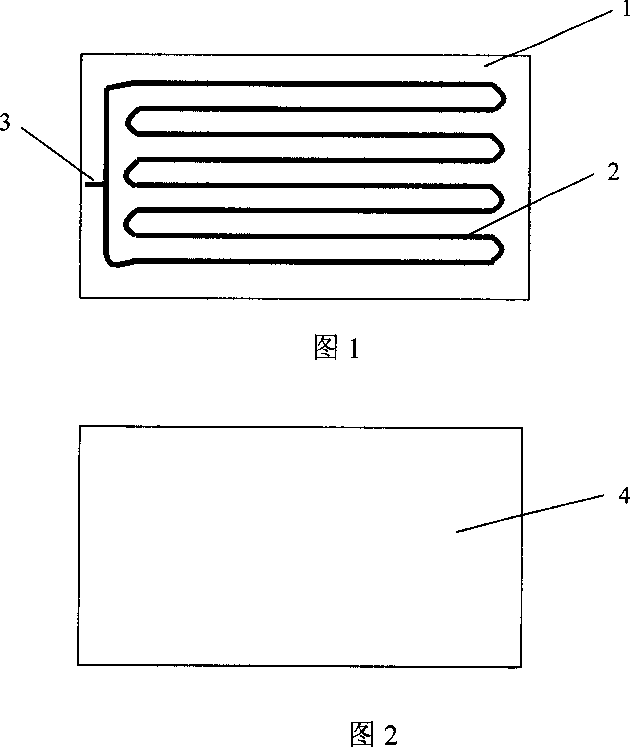
[0019] As shown in Figures 1 and 2, the pulsating heat pipe heat sink with microcapsule phase change thermal storage fluid as the working medium includes a base plate 1 and a cover plate 4, and the base plate 1 and cover plate 4 together form a completely closed cavity; the base plate 1 has a serpentine groove 2, the number of bends in the serpentine groove 2 is 8, and the cross section is a rectangle of 0.5mm×0.5mm; the serpentine groove 2 is equipped with microcapsule phase change heat storage fluid FS-39E fluid The serpentine groove 2 of the working medium communicates with the inlet 3 on the substrate 1 . Microcapsule phase change heat storage fluid FS-39E is one of the series of heat storage materials produced by Mitsubishi Paper Co., Ltd., with a phase change temperature of...


PUM


Abstract

The invention discloses a pulse heat tube radiating plate which uses the phase-variable fluid of micro capsule as work medium, comprising a base plate (1) and a cover plate (4) to form a sealed chamber. The base plate (1) is arranged with a curved groove (2) with at least two bended heads and the section diameter of groove is smaller than 2mm. the groove (2) contains the phase-variable fluid medium, while the groove (2) is communicated with the inlet (3) of base plate (1). The fluid medium is FS-39E micro capsule phase-variable material. The invention can avoid movable element and noise while it is driven by waste heat completely.

Description

technical field [0001] The invention relates to a heat pipe type cooling plate, in particular to a pulsating heat pipe type cooling plate using a microcapsule phase change thermal storage fluid as a working medium. Background technique [0002] With the continuous development of the electronic industry, the functions and complexity of electronic equipment are increasing day by day. Within a limited volume range, the power consumption of electronic equipment continues to increase, and the amount of heat dissipation increases sharply. Taking microelectronic chips as an example, the current heat flux has reached 60-90W / cm 2 , up to 200W / cm 2 . The traditional convective heat transfer method and forced air cooling method relying on single-phase fluid can only be used for heat flux density not greater than 10W / cm 2 For electronic devices, the heat flux has reached 600W / cm 2 The above situation has become impotent. The heat dissipation and cooling of electronic components has...

Claims


Application Information

Patent Timeline
Patent Type & Authority Applications(China)
IPC IPC(8): F28D15/02H05K7/20
CPCF28D15/0266
Inventor 汪双凤
Owner SOUTH CHINA UNIV OF TECH
Why Eureka
Try Eureka