

Measurement and control pressure testing system of petroleum well control device
A technology for oil wells and pressure testing, applied in general control systems, control/regulation systems, measuring devices, etc., to achieve the effects of improving quality assurance capabilities, ensuring safety, and ensuring factory pass rates
- Summary
- Abstract
- Description
- Claims
- Application Information
AI Technical Summary
Problems solved by technology
Method used
Image

Examples
Embodiment 1
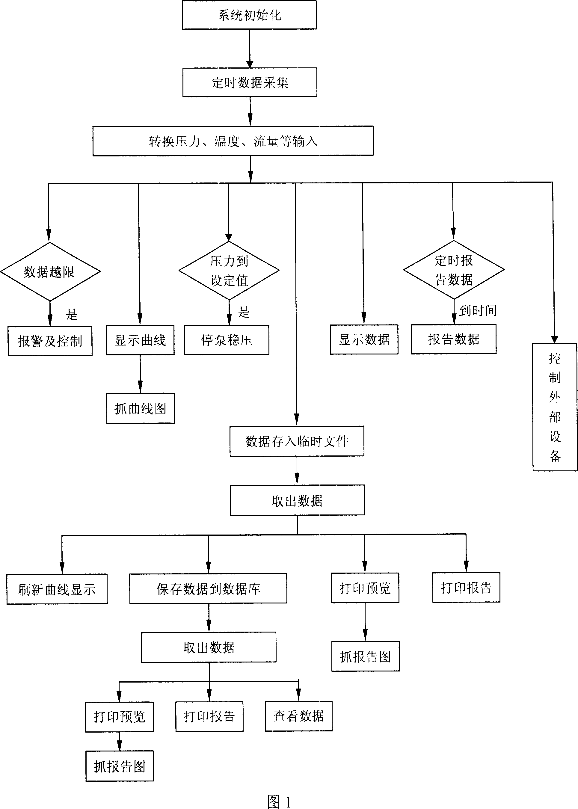
[0039] As shown in Figure 1, the oil well control device measurement and control pressure test system includes a virtual instrument system for collecting, controlling and analyzing data. The virtual instrument system includes hydraulic clamps, hydraulic power stations, pressure test pumps, industrial control Computer, data acquisition module, data processing module, automatic control module; the virtual instrument system collects data by connecting the data acquisition module with the solenoid valve and pressure temperature sensor installed on the hydraulic power station and pressure test pump group, and then processes it through the data processing module Finally, the automatic control module automatically controls the operation of the hydraulic power station and the pressure test pump group.
[0040] The hydraulic clamp is a special clamping tool for wellhead devices, equipped with sensors and non-contact switches, and has actions such as clamping, loosening, jacking up, pull...
Embodiment 2
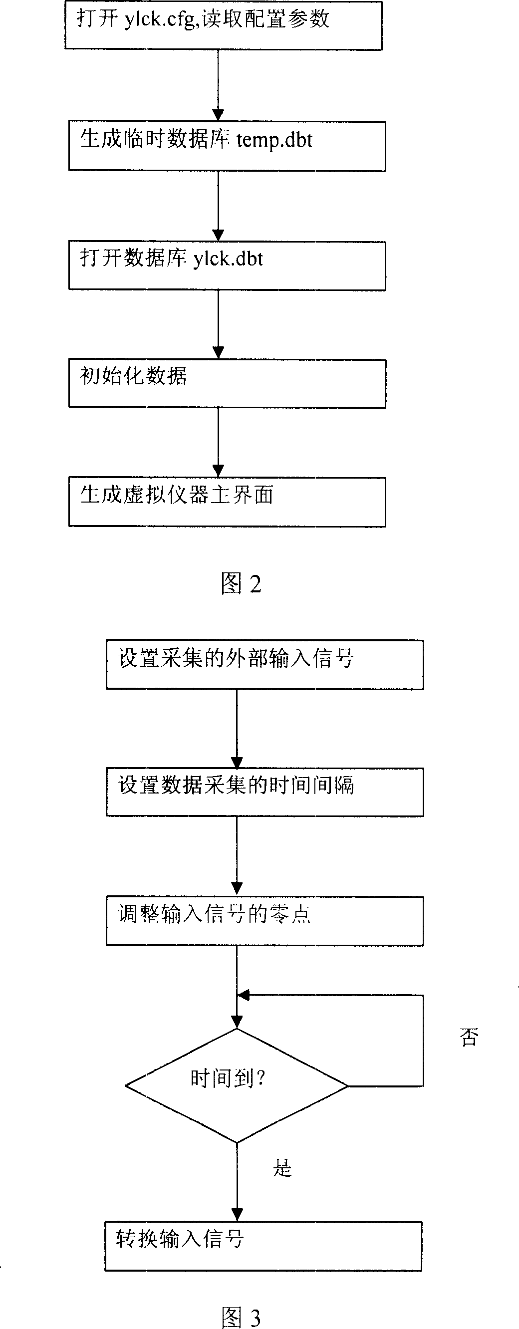
[0058] As shown in Figure 2, the configuration parameters of this system are saved with a file ylck.cfg, and the virtual instrument is initialized according to the default configuration of the system. The system uses ylck.dbt to save the signal data collected from the sensor, and uses temp.dbt to save the signal data collected temporarily.
[0059] The ylck.cfg configuration file is an Access database, which has a table: setup, and there are three fields in the table: Type, Name, and Data, all of which are text types. It is used to save the number of acquisition channels, displayed curve color, sensor range, sensor calibration zero point and full scale, alarm size, alarm sound, stored test related information, etc.
[0060] The temporary database file temp.dbt is used to save the current collection data. Among them is the table temp, which is to save the data obtained since the start of the test data, including ID, time, channel 0 to channel n, and the types of these fields a...
Embodiment 3
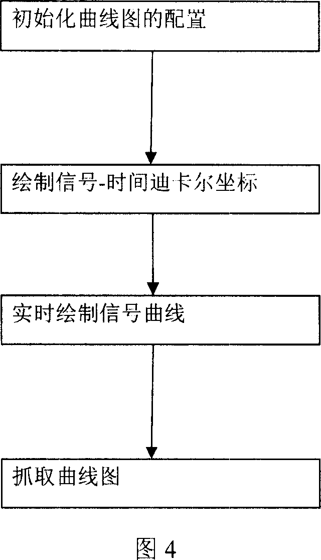
[0065] As shown in Figure 3, the data acquisition module regularly collects externally input signals such as pressure, temperature, and flow. Users can adjust the time interval of collection, and also change the type, range, and display of the collected signals. It is the core module of system performance, and the applicability of system application depends largely on the optimization degree and rationality of this module.
[0066] The program data, performance and design of this module are described as follows:
[0067] A. The external input signal of the virtual instrument is a current of 4~20mA, which is converted into a 1~5v input by using a 250 ohm high-precision resistor. The use of current remote transmission can avoid the interference of the length of the signal line on the signal.
[0068] B. Virtual instruments can convert analog signals to digital signals and digital signals to analog signals. The analog-to-digital conversion precision of the linearizer is 12 bits...
PUM
 Abstract
Description
Claims
Application Information