Method for detecting plant electric signal in green house and special equipment thereof

An electrical signal, plant technology, applied in the field of agricultural information, can solve problems such as damage, discomfort in greenhouse applications, plant connection and fixation troubles, etc.

Inactive Publication Date: 2007-08-22
CHINA AGRI UNIV
View PDF0 Cites 16 Cited by
  • Summary
  • Abstract
  • Description
  • Claims
  • Application Information

AI Technical Summary

Problems solved by technology

The existing detection techniques mainly include the following: (1) Ag-AgCl silver-silver chloride electrodes are used to measure action potentials and variation potentials in a short period of time, but the drift of the electrode potential can reach 1.88mV / h and in the presence of light Long-term use in the environment will cause light damage to the Ag-AgCl electrode [4] , Ag-AgCl electrodes cannot be used for long-term monitoring of plant electrical signals in an environment with light; And it will also affect the transport of substances from the phloem to the organic body; (3) Although the calomel electrode is used for measurement, long-term monitoring is not considered, and the salt bridge used to connect the electrode to the plant is fully open, so that the concentration of the solution continues to increase. The part of the plant connected to it is dehydrated, the impedance transformer is not used in the measurement, and it is troublesome to connect and fix the plant [12] (4) It must be operated in a Faraday cage, and it cannot really be used in a greenhouse environment for a long time; (5) Directly use electrodes, amplification circuits and acquisition circuits for measuring animals and human bioelectricity, and circuit design errors lead to inability to monitor and detect The electrical signal cannot be output in a greenhouse environment. From the design disclosed in the literature, the circuit shown in Figure 8A is adopted. Due to the existence of two semiconductor diodes at the input terminals D1 and D2, the input impedance cannot meet the requirements of the plant electrical signal, so the acquisition As shown in Figure 8B, a certain rhythm is present, which generally appears on some specialized cells such as animal and human cardiomyocytes, and the essence is that the Na on the cell membrane + ion channel or Na + The ion pump has a certain rhythm of opening and closing to automatically depolarize the cell membrane potential, and there is no Na on the cell membrane of the plant cell itself. + ion channel or Na + ion pump [6] , there is no mechanistic basis for automatic depolarization of the membrane potential, and the rhythmic changes acquired are disturbances rather than signals [7][8][9] ; This phenomenon also exists in other relevant literature reports [10] (6) Directly adopt electrodes, amplifying circuits and acquisition circuits for measuring animals and human bioelectricity. Since plants experience vegetative growth and reproductive growth stages from the seedling stage, their epidermis cells are constantly differentiated and keratinized, which is equivalent to The internal resistance of the signal source continues to increase, and the current bioelectricity monitoring method for the human body cannot meet the requirements of long-term, non-destructive detection of plant electrical signals
[0004] In summary, the currently used methods for detecting plant electrical signals (prior art) are short-term and lossy, and are not suitable for long-term monitoring of plant electrical signals in greenhouses. [5] ; or directly adopt the monitoring method of measuring animal and human bioelectricity, which cannot complete the long-term monitoring of plant electrical signals; plant electrical signals are weak signals that are easily interfered, and have been shielded by Faraday cages in the past, which is not suitable for application in greenhouses; the existing technology cannot provide Further analysis method and steps of plant electric signal

Method used


Image

  • Method for detecting plant electric signal in green house and special equipment thereof
  • Method for detecting plant electric signal in green house and special equipment thereof
  • Method for detecting plant electric signal in green house and special equipment thereof

Examples


Embodiment Construction

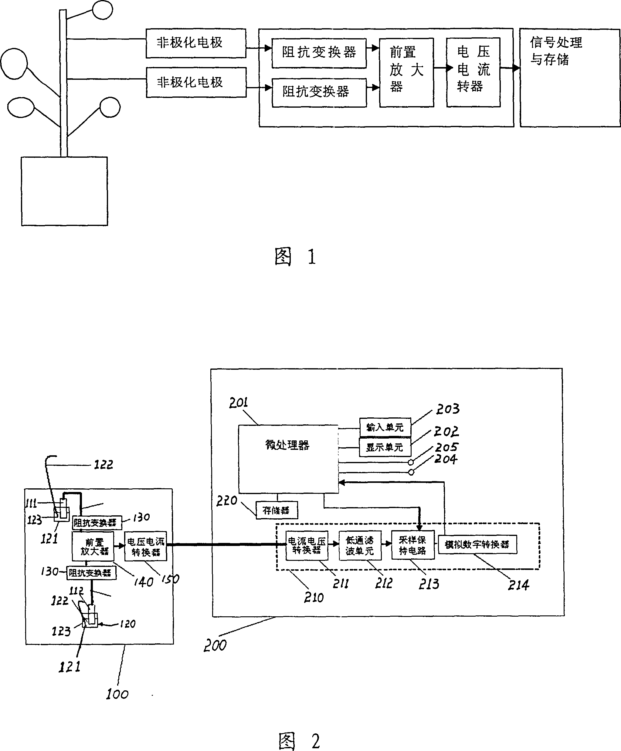
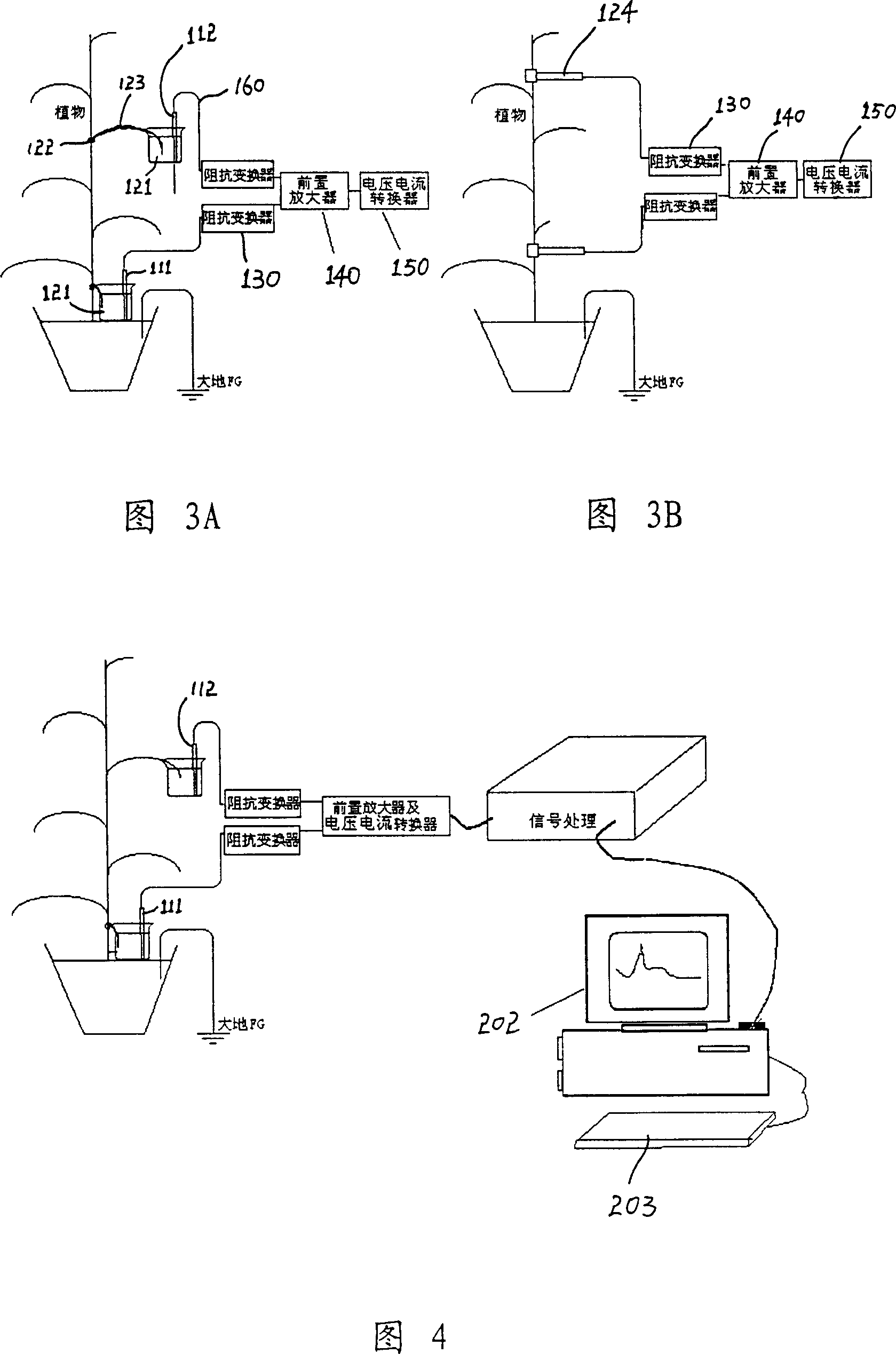
[0071] First, as shown in Figures 1 to 4, it is a device for detecting electrical signals of plants in a greenhouse provided by the present invention, which includes a signal detection device 100 and a signal processing device 200;

[0072] The signal detection device 100 includes two electrodes 111, 112 and an electrode connection device 120, the output end of each electrode is connected with an impedance converter 130, and the signal output end of each impedance converter 130 is connected with a preamplifier 140, the preamplifier The output terminal connected to 140 is connected to a voltage-to-current converter 150;

[0073] The signal processing device 200 includes a signal processing circuit 210 connected to the voltage-to-current converter 150 , and a microprocessor 201 connected to the signal processing circuit 210 . The microprocessor 201 is also connected to a memory 220 for storing data.

[0074] In the present invention, the signal processing circuit 210 specifically ...


PUM


Abstract

The invention discloses a method and a special device to detect electric signal of greenhouse plant. Its steps are: (1) Takes unpolarized electrode as reference and measuring electrode. (2) Connects electrode and plant stems or leaves without consuming by electrode linkage unit. (3) Adopts impedance transformer with its input impedance greater than 1012Omega to connect with output port of electrode separately. Signal output port of each impedance transformer is connected with a preamplifier, whose output signal is transferred to current signal by a voltage-current converter sending to signal processing unit for processing. The invention can long-term detect change of plant electric signal without consuming, process weak plant electric signal to separate signal and noise. When environment factor changes, it can calculate and detect main factor causing changes of plant electric signal by some arithmetic, which provides premise condition for plant electric signal detecting transferring from lab research to service and production.

Description

technical field [0001] The invention relates to the field of agricultural information technology, in particular to a method and special equipment used in greenhouses for long-term monitoring of electrical signals of herbaceous plants. Background technique [0002] When plants are stimulated by environmental changes, they will produce corresponding extracellular signal transmission (such as chemical signals, water signals and electrical signals) [2] , and the occurrence and transmission of electrical signals may be the initial response of plants to external stimuli, which can trigger physiological changes [3] (such as: elongation growth, respiration, water absorption, phloem material unloading, turgor pressure drop, changes in photosynthesis and transpiration, gas exchange, activation of protease inhibitor genes, transcription, etc.), thereby coordinating various organs in the plant, The relationship between organizations and between themselves and the external environment ...

Claims


Application Information

Patent Timeline
Patent Type & Authority Applications(China)
IPC IPC(8): G01N33/00G01N27/00G06F19/00
Inventor 黄岚王忠义刘志存徐志龙史银雪吕春利劳彩莲赵龙莲
Owner CHINA AGRI UNIV
Why Eureka
Try Eureka