Micro phase delay capacity light delay linear array switch

A phase delay and optical delay line technology, applied in optics, optical components, nonlinear optics, etc., can solve the problems of large insertion loss, difficult adjustment of small phase delay, large volume of variable optical delay devices, etc. The effect of small structure and small signal loss

Inactive Publication Date: 2007-08-22
ZHEJIANG UNIV
View PDF0 Cites 14 Cited by
  • Summary
  • Abstract
  • Description
  • Claims
  • Application Information

AI Technical Summary

Problems solved by technology

[0007] The purpose of the present invention is to solve the defects of large volume, large insertion loss and difficult adjustment of small phase delay in the variable optical delay device composed of digital binary optical delay line multi-stage serial connection structure, and provide a small phase delay optical Delay Line Array Switching Devices

Method used


Image

  • Micro phase delay capacity light delay linear array switch

Examples


Embodiment Construction

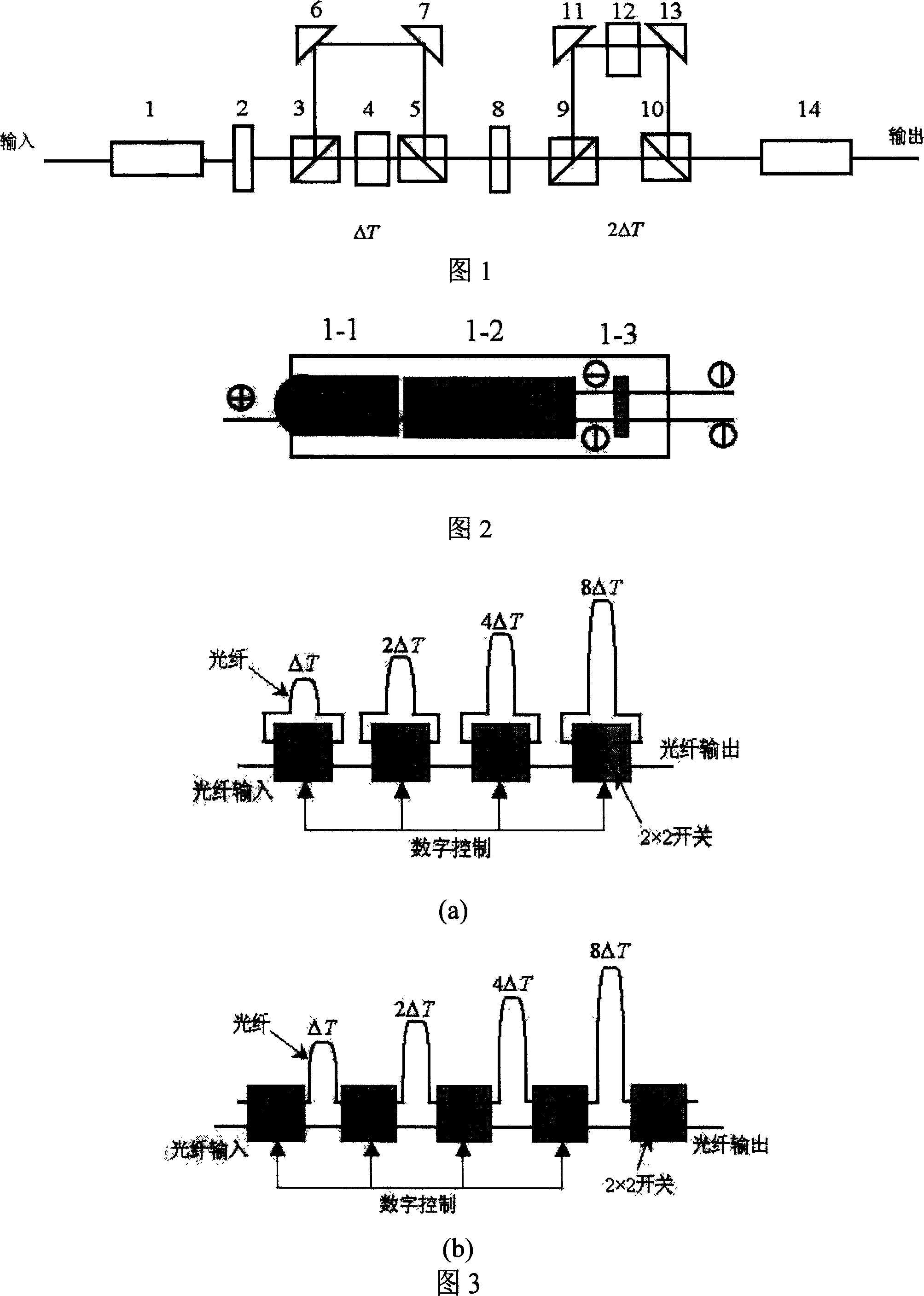
[0015] As shown in Figure 1, the small phase delay optical delay line array switch is to place the first single fiber polarization beam splitter collimator 1, the first polarization rotation switch 2, the first polarization splitter 3, The first delay compensation film 4, the first polarization combiner 5, the second polarization rotary switch 8, the second polarization splitter 9, the second polarization combiner 10, the second single-fiber polarization splitting collimator 14, The first micro-mirror 6 is placed on the vertical optical path of the first polarization splitter 3, and the second micro-mirror 7 is placed on the vertical optical path of the first polarization combiner 5; the third micro-mirror 11 is placed on the second On the vertical optical path of the polarization splitter 9, the fourth micro-mirror 13 is placed on the vertical optical path of the second polarization combiner 10; the second retardation compensation film 12 is placed on the third micro-mirror 11...


PUM


Abstract

The invention discloses a micro phase delay quantity light delay line array switch, on the same horizontal light path, in turn placing first single optical fiber polarization beam splitting collimator, first polarization rotating switch, first polarization distributor, first delay compensation plate, first polarization combiner, second polarization rotating switch, second polarization distributor, second polarization combiner, and second single optical fiber polarization beam splitting collimator, where the first micro reflector is placed on the vertical light path of the first polarization distributor, the second micro reflector is placed on the vertical light path of the first polarization combiner; the third micro reflector is placed on the vertical light path of the second polarization distributor, and the fourth micro reflector is placed on the vertical light path of the second polarization combiner; the second delay compensation plate is placed between the third and fourth micro reflectors and they together form the same horizontal light path. And it can implement 0-0.6ns delay, suitable to micro light delay control and regulation; and has advantages of small device bulk and low signal loss.

Description

technical field [0001] The invention relates to an optically controlled phase delay line array switch used for variable phase shifters in microwave, millimeter wave and submillimeter wave transmission systems. Background technique [0002] Traditional phase shifters used in microwave, millimeter wave, and submillimeter wave transmission systems are realized through electrical regulation technology, that is, the control and adjustment signals of the variable phase shifter are electrical signals. The most commonly used is to use the interaction of materials such as ferrite or semiconductor diodes with electromagnetic waves to produce phase shifting. The basic principle of the ferrite phase shifter is to change the magnetic susceptibility of the ferrite by changing the additional magnetic field of the ferrite, thus changing the phase velocity of the electromagnetic wave to obtain different phase shifts. The diode phase shifter is to place one or more diodes in the microwave wa...

Claims


Application Information

Patent Timeline
Patent Type & Authority Applications(China)
IPC IPC(8): G02B6/27G02B27/28G02F1/01
Inventor 金晓峰池灏章献民
Owner ZHEJIANG UNIV
Why Eureka
Try Eureka