Condenser miniature silicon microphone and preparative method

A silicon microphone and capacitive technology, applied in the field of micro-electro-mechanical systems, can solve the problems of complex implementation, increased processing complexity, and ineffective reduction of residual stress, etc., to reduce chip area and improve design flexibility Effect

Inactive Publication Date: 2007-08-22
MEMSENSING MICROSYST SUZHOU CHINA
View PDF0 Cites 26 Cited by
  • Summary
  • Abstract
  • Description
  • Claims
  • Application Information

AI Technical Summary

Problems solved by technology

Residual stress has a great influence on the characteristics of the micro-silicon microphone, and even makes it fail to work in severe cases
Furthermore, a large residual tensile stress will also significantly reduce the mechanical sensitivity of the vibrating membrane, and the mechanical sensitivity of the vibrating membrane is directly proportional to the key index of the microphone—sensitivity, so a large residual stress will indirectly lead to a decrease in the sensitivity of the microphone
In addition, large residual compressive stress may also cause the diaphragm to buckle, making the performance of the microphone unstable or even failure
[0006] Therefore, improving the sensitivity of the microphone has become the focus of attention of those skilled in the art. The existing method of improving the process conditions of the preparation method deposition, or using some additional processes Such as annealing to reduce the residual stress of the vibrating membrane, but this method has little effect on reducing the residual stress, and the repeatability is not good, and the realization is more complicated; another way is to suspend the vibrating membrane and make the vibrating membrane The mechanical sensitivity is not sensitive to residual stress, but this method often leads to increased processing complexity

Method used


Image

  • Condenser miniature silicon microphone and preparative method
  • Condenser miniature silicon microphone and preparative method

Examples


Embodiment approach 1

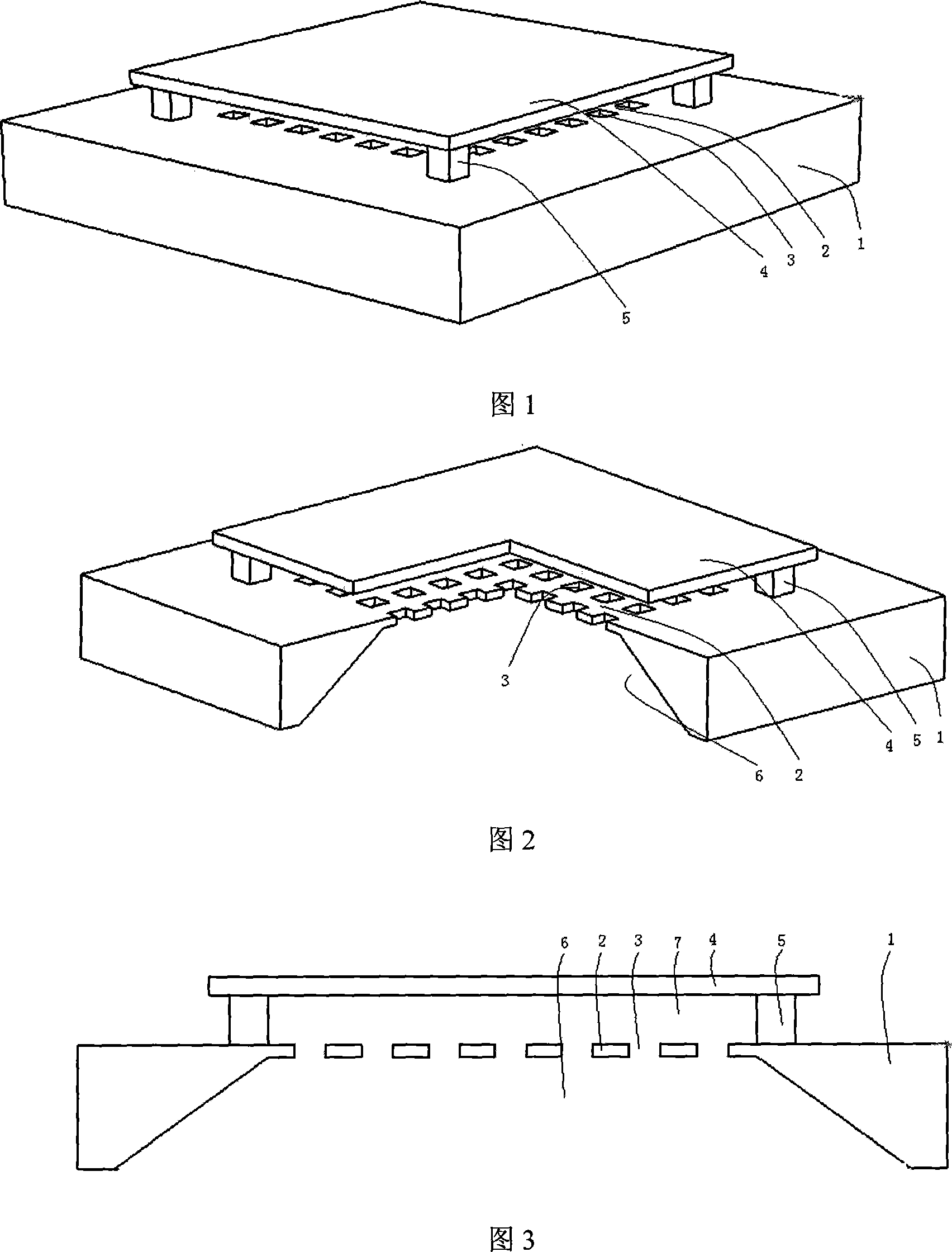
[0018] Please refer to FIG. 1 to FIG. 3 , the capacitive miniature silicon microphone of the present invention includes: a back plate, a vibrating membrane, an insulating support body, and the like.

[0019] The back plate 2 has a conductive function and is used as one pole of a capacitor. During manufacture, a back cavity 6 is first formed on a silicon substrate by an isotropic or anisotropic processing method, and then the back cavity 6 is obtained while the back cavity 6 is obtained. Combined with self-stop technology (such as heavy doping), the back plate 2 can be formed, wherein the substrate 1 can be low-resistance silicon, or glass with a metal-covered surface, which acts as a mechanical support, and then passes through the back plate 2. Multiple acoustic holes 3 can be obtained by means of selective doping or photolithography. Multiple acoustic holes 3 can play the role of propagating sound pressure and adjusting the damping between the vibrating membrane and the back p...

Embodiment approach 2

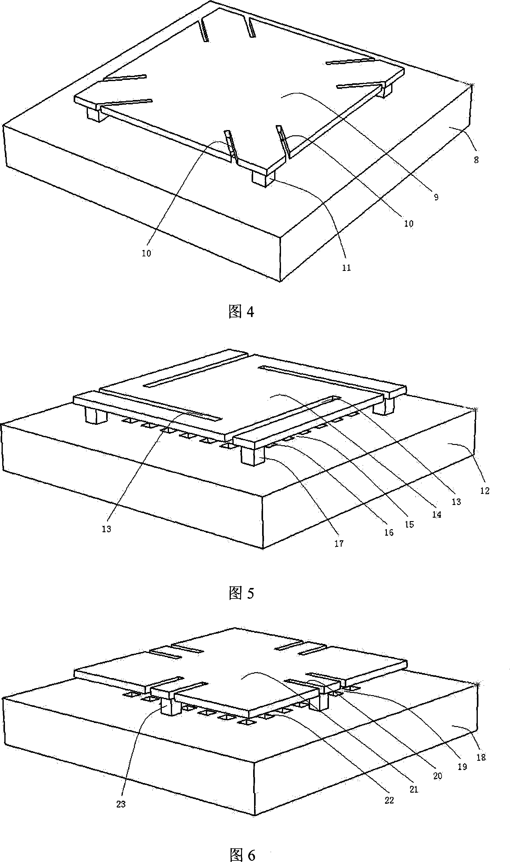
[0021] Please refer to Fig. 4, this embodiment mode is similar to embodiment mode one, and substrate 8 can be low-resistance silicon, or the glass that has metal covering surface, plays mechanical supporting role; Silicon nitride, etc., the mechanical support of the vibrating film 9 is completed by connecting the insulating support body 11, which acts as an insulating support, to the back plate at the four corners of the vibrating film. The insulating support body can be made of silicon dioxide or silicon nitride, etc. Insulation materials alone or in combination. The rest of the back plate, back cavity and sound holes are the same as in Embodiment 1.

[0022] The difference from Embodiment 1 is that there are a plurality of narrow grooves 10 on the vibrating membrane, and the plurality of narrow grooves are two parallel short slits respectively. The angle extends toward the center of the vibrating membrane, adding narrow grooves 10 can provide more design flexibility and imp...

Embodiment approach 3

[0024] Please refer to Fig. 5. This embodiment is the same as Embodiment 2 except that the shape, size, quantity and position of the grooves on the vibrating membrane are different. In this embodiment, the plurality of narrow grooves are formed by the A long slit extending from the edge of the vibrating membrane and parallel to the corresponding side of the vibrating membrane.


PUM


Abstract

A micro-silicon microphone of capacity type is prepared using back electrode plate with conduction function as one electrode of capacity and using vibration membrane with conduction function as another electrode of capacity, using multiple insulation support to support vibration membrane, firm-jointing said supports with vibration membrane and back electrode plate and arranging narrow groove on said vibration membrane for making vibration membrane be not sensitive on residual stress.

Description

technical field [0001] The invention belongs to the field of micro-electro-mechanical systems (MEMS) based on silicon technology, and in particular relates to a capacitive micro-silicon microphone and a preparation method thereof. Background technique [0002] MEMS technology is a high-tech that has developed rapidly in recent years. Compared with traditional counterparts, MEMS devices have obvious advantages in volume, power consumption, weight and price, and they adopt advanced semiconductor manufacturing processes. Batch manufacturing of MEMS devices. Currently on the market, the main application examples of MEMS devices include pressure sensors, accelerometers and silicon microphones. [0003] For silicon microphones, an automated surface mount process is usually used to assemble them to a circuit board, which requires high temperatures, and traditional electret microphones (ECMs) will leak charges at high temperatures, causing the ECM to fail, so ECMs are assembled only...

Claims


Application Information

Patent Timeline
Patent Type & Authority Applications(China)
IPC IPC(8): H04R19/01H04R19/04H04R31/00
Inventor 胡维李刚
Owner MEMSENSING MICROSYST SUZHOU CHINA
Why Eureka
Try Eureka