
Method and apparatus for ultrashort pulse laser parallel fine machining

An ultrashort pulse laser and ultrashort pulse technology, which is applied in laser welding equipment, metal processing equipment, welding equipment, etc., can solve the problems of low processing efficiency of ultrashort pulse laser, and achieve small indirect damage, high precision and high processing efficiency. high effect

Inactive Publication Date: 2007-09-05
XI'AN INST OF OPTICS & FINE MECHANICS - CHINESE ACAD OF SCI
View PDF0 Cites 29 Cited by
  • Summary
  • Abstract
  • Description
  • Claims
  • Application Information

AI Technical Summary

Problems solved by technology

[0005] The object of the present invention is to provide a parallel ultrashort pulse laser micromachining method and equipment, which solves the technical problems of traditional laser processing such as recast layers and microcracks in the background technology and very low ultrashort pulse laser processing efficiency.

Method used


Image

  • Method and apparatus for ultrashort pulse laser parallel fine machining
  • Method and apparatus for ultrashort pulse laser parallel fine machining
  • Method and apparatus for ultrashort pulse laser parallel fine machining

Examples


Embodiment Construction

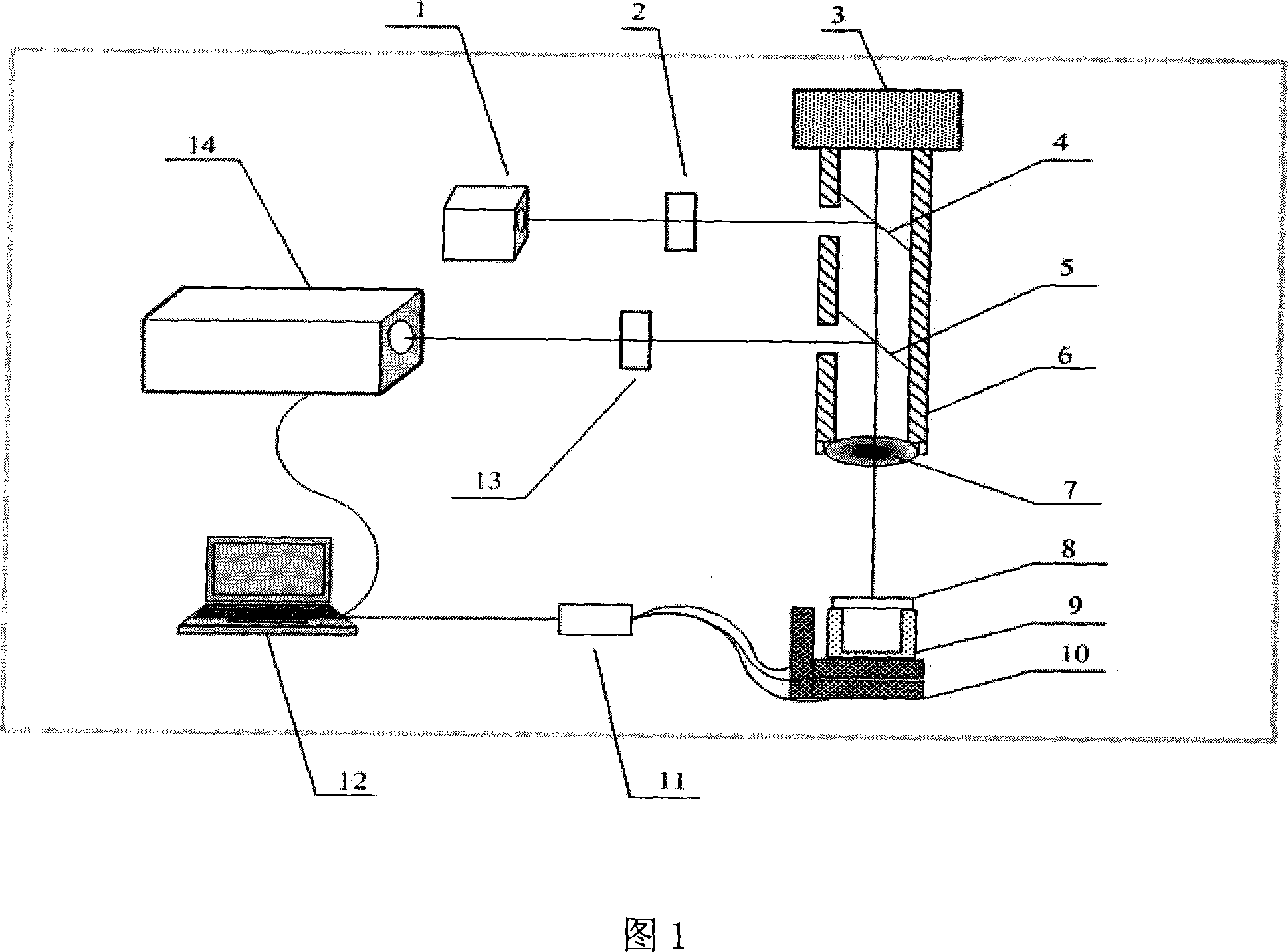
[0031] A kind of processing equipment that realizes the method of the present invention used is as shown in Figure 1, and ultrashort pulse laser system 14 adopts femtosecond laser system, and the femtosecond laser beam of its output becomes the laser light of multi-beam divergence after microlens array 13, Multiple beams of laser light are incident into the metal cylinder 6 equipped with 800nm ​​45-degree laser mirror 5, reflected vertically downward, and focused on the sample 8 to be processed through the focusing system 7, correspondingly forming multiple focal points on the focal plane. The distribution of laser light at the focal plane depends on the distribution of each small lens in the microlens array, and the size depends on the size of a single lens in the microlens array and the optical magnification of the focusing system 7 . The sample to be processed 8 is installed on the hollow sample stage 9, and the hollow sample stage 9 mainly prevents the femtosecond laser fro...


PUM


Abstract

A parallel ultra-short pulse laser micromachining technology is characterized by that an ultra-short pulse laser beam passes through a microlense array to become multiple divergent ultra-short pulse laser beams, which are then focused onto a focal plane on a workpiece by a focusing system for micromachining on it. Its apparatus is also disclosed.

Description

technical field [0001] The invention relates to a method and equipment for ultrashort pulse laser processing. Background technique [0002] Laser machining is a non-contact material cutting process that removes material by melting and vaporizing, so it is especially suitable for processing hard and brittle materials. Traditional laser (nanosecond, microsecond pulse or continuous laser) processing has high efficiency and has been accepted by the industry as an economical and competitive technical means. However, since the laser pulse is longer than the thermal diffusion time, processing defects such as recast layers and microcracks are inevitable. These defects not only reduce the mechanical properties of the workpiece, but also pose hidden dangers to safe service. Although the drilling quality can be improved by improving the laser processing technology, subsequent processes such as defect removal and stress relief annealing are still required. [0003] In the mid-1990s, ...

Claims


Application Information

Patent Timeline
Patent Type & Authority Applications(China)
IPC IPC(8): B23K26/067B23K26/04B23K26/06B23K26/42B23K26/046B23K26/70
Inventor 程光华陈国夫赵卫王屹山温泉许正芳
Owner XI'AN INST OF OPTICS & FINE MECHANICS - CHINESE ACAD OF SCI
Learn More