
Coupling system of oscillator

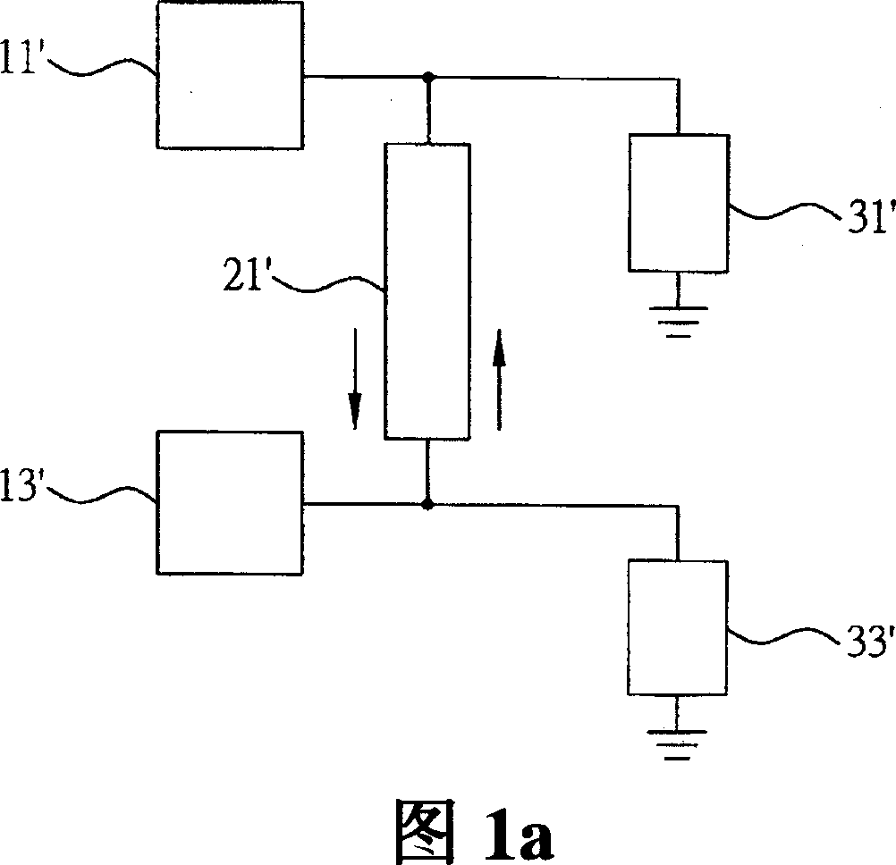
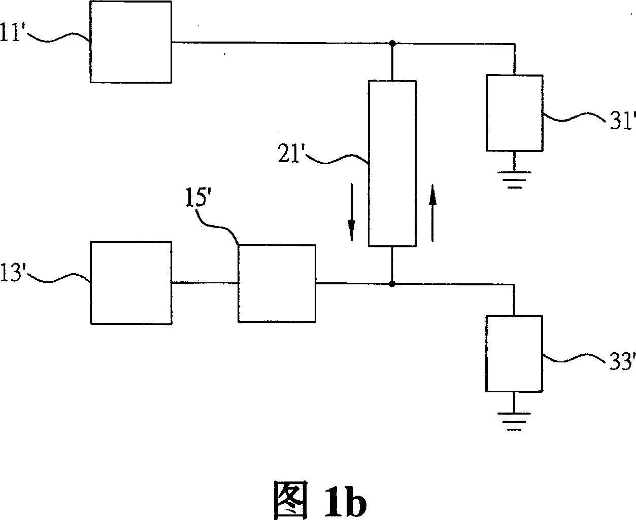
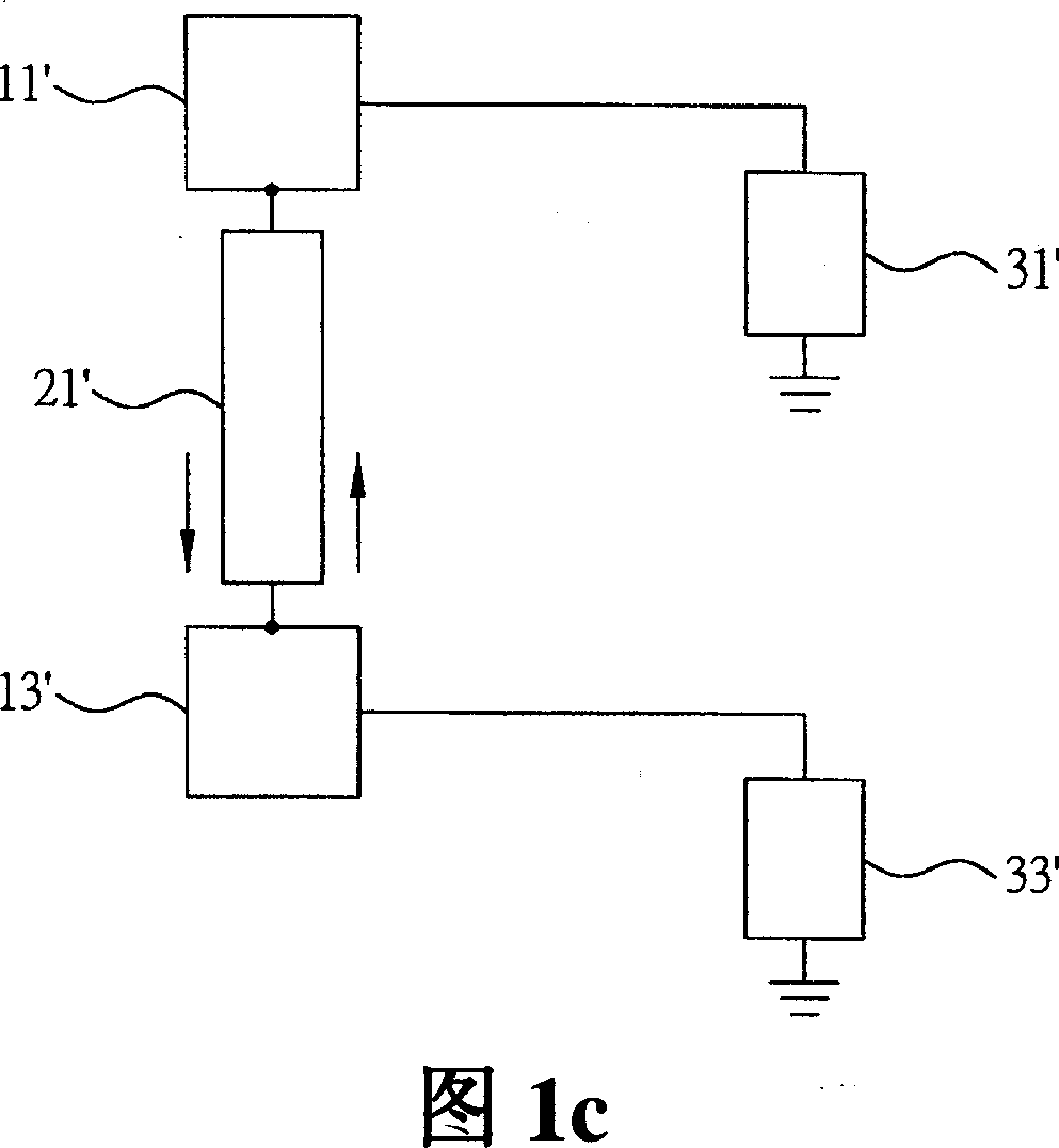
A technology for coupling systems and oscillators, applied in power oscillators, electrical components, automatic control of power, etc., can solve problems affecting the minimum detectable signal power of the system, the limitation of effective signal transmission and reception distance, and the limitation of signal-to-noise ratio. , to achieve the effect of increasing system stability, changing input and output impedance, and increasing bandwidth

Inactive Publication Date: 2007-09-05
张恒嘉
View PDF0 Cites 2 Cited by
  • Summary
  • Abstract
  • Description
  • Claims
  • Application Information

AI Technical Summary

Problems solved by technology

[0008] However, due to the advancement of science and technology, the frequency of satellite communication, satellite network, satellite positioning, and wireless network is getting higher and higher, which has reached tens of MHz to tens of GHz. The aforementioned technology of coupling at least two oscillators If the influence of noise cannot be reduced more effectively, the signal-to-noise ratio of the entire communication system will be limited, which will affect the minimum detectable signal power of the system, so that the effective transmission and reception distance of the signal is limited, and there is a bandwidth insufficient problems arise
[0009] Therefore, how to effectively solve the problems existing in the above technologies, and develop a system that can meet the requirements of high-frequency circuits and have better phase or frequency noise suppression effects, so as to increase the system operating bandwidth, improve operating efficiency and avoid phase or frequency noise Affecting the output effect is an urgent problem to be solved in related fields

Method used


Image

  • Coupling system of oscillator
  • Coupling system of oscillator
  • Coupling system of oscillator

Examples


Embodiment Construction

[0037] The following describes the implementation of the present invention through specific examples, and those skilled in the art can easily understand other advantages and effects of the present invention from the content disclosed in this specification

[0038] Please refer to FIG. 2, which is a schematic block diagram of the oscillator coupling system of the present invention. As shown in the figure, the oscillator coupling system of the present invention includes a plurality of oscillating elements 11 and 13; it is connected between at least two oscillating elements 11 and 13 and a second delay element 23 connected between the at least two oscillating elements 11 and 13 and in parallel with the first delay element 21, through which the second delay element 23 introduces The phase or time delay parameter of the first delay element 21 at least several times or more (that is, the phase or time delay difference between the second and the first delay element is more than severa...


PUM


Abstract

The invention is concerned with the oscillator coupled system, consists of: several oscillation elements and several delay elements, the delay element connects with at least two oscillation elements, several delay elements have special phase or time delay relation, couplings the phase or the frequency noise suppression correlation characteristic of at least two oscillation elements by the delay element, reduces the noise automatic pertinence in the circuit system operation, in order to gain phase or the frequency noise suppression effect, avoid to use the solid circulator, the isolator and the resonant cavity, reduce the signal distortion and increase the system stabilization.

Description

technical field [0001] The present invention relates to a noise reduction technology, in particular to an oscillator coupling system applied to provide phase or frequency noise suppression in high frequency / low frequency environments. Background technique [0002] In communication circuits and electronic systems, noises generated by signal sources or oscillation generating components will limit the overall efficiency of the system. Among them, there are many reasons for noise interference, such as lightning strikes, switching of peripheral load equipment, generators, Radio communication, poor wire contact, poor switch engagement, improper grounding and radio wave interference, etc. If the phenomenon of noise generation is not eliminated, it will easily lead to random errors in data file access or executable files on storage devices, and it will easily cause abnormal operations of calculators and controllers or interfere with communication systems on electronic products. [...

Claims


Application Information

Patent Timeline
IPC IPC(8): H03B1/00H03L7/00
Inventor 张恒嘉
Owner 张恒嘉
Learn More