Device for cutting glass substrate and its method

A technology of cutting equipment and cutting method, which is applied in the direction of metal processing equipment, welding equipment, glass manufacturing equipment, etc., and can solve the problems of misalignment of cutting surfaces, inability to accurately control the cutting depth of glass substrates, and lower product quality.

Active Publication Date: 2007-09-05
TOP ENG CO LTD
View PDF1 Cites 31 Cited by
  • Summary
  • Abstract
  • Description
  • Claims
  • Application Information

AI Technical Summary

Problems solved by technology

Once a correction error occurs, it will cause the cutting surface to misalign, thereby reducing product quality
[0015] In particular, the above-men

Method used


Image

  • Device for cutting glass substrate and its method
  • Device for cutting glass substrate and its method
  • Device for cutting glass substrate and its method

Examples


Embodiment Construction

[0032] Reference will now be made in detail to the preferred embodiments of the present invention, examples of which are illustrated in the accompanying drawings. Like reference numerals refer to like elements throughout the drawings of the specification.

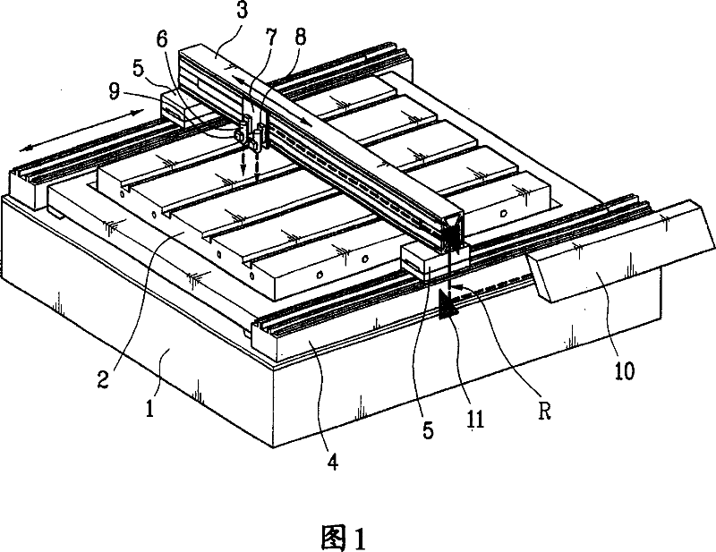
[0033] FIG. 1 is a perspective view of a non-metallic substrate cutting apparatus for manufacturing a flat panel display according to one embodiment of the present invention.

[0034]Referring to FIG. 1, a non-metallic substrate cutting device for manufacturing a flat panel display according to an embodiment of the present invention includes: a workbench 2, which is arranged on a central portion of a base 1 to support a glass substrate (not shown in the drawings) ; The front and rear guide columns 4 are respectively arranged on both sides of the workbench 2 ;

[0035] Left and right guide columns 3 are arranged on each pusher 5 to guide a laser head 6 to move in left and right directions. Moreover, the left and right guid...


PUM


Abstract

An apparatus for cutting a nonmetallic substrate (P) and method thereof are disclosed. The present invention is suitable for cutting upper and lower substrates (P) simultaneously or for cutting either an upper or lower substrate selectively in a manner of controlling a cutting depth by adjusting a focus position of a short wavelength laser beam in cutting various nonmetallic substrates (P) such as a glass substrate for fabricating a flat panel display such as TFT-LCD, PDP, OLED, etc. The present invention includes a laser beam generator (10) generating a UV short wavelength laser beam, a torch (6) applying the short wavelength laser beam to a specific location on the nonmetallic substrate to be cut, a focus moving means (8) for varying a focus location of the laser beam in a depth direction of the substrate, and a relative object moving means (3, 4) for allowing the substrate and the laser beam to make a relative movement to cut the substrate.

Description

technical field [0001] The present invention relates to a kind of non-metallic substrate cutting equipment and method thereof, especially suitable for cutting various non-metallic In the case of glass substrates for flat-panel displays such as light-emitting displays (OLEDs), the upper and lower substrates are simultaneously cut, or the upper and lower substrates are selectively cut by adjusting the focus position of the short-wavelength laser beam to control the cutting depth. Background technique [0002] Generally speaking, in the manufacture of flat display devices such as thin-film transistor-liquid crystal display (TFT-LCD), plasma display (PDP), organic light-emitting display (OLED), etc., the glass substrate must be cut after the pretreatment of the unit process is completed. to match the size of each module. In addition, it is also necessary to selectively cut the glass of the upper plate only on the bonded substrate. [0003] A glass cutting method according to t...

Claims


Application Information

Patent Timeline
IPC IPC(8): B23K26/40C03B33/037C03B33/02C03B33/07
CPCB23K26/04C03B33/076C03B33/0222B23K26/4075B23K26/40B23K2103/50A45D33/20A45D40/22A45D40/24A45D2033/001A45D2040/225
Inventor 方圭龙李昌馥金钟郁金永敏
Owner TOP ENG CO LTD
Why Eureka
Try Eureka