System and method for transforming low temperature residual heat into steam

A low-temperature waste heat and steam technology, applied in intersecting fields, can solve the problems of low thermal efficiency and low steam pressure, and achieve the effects of low equipment cost, simple process and high heat recovery efficiency

Inactive Publication Date: 2007-09-12
UNIV OF SCI & TECH BEIJING
View PDF0 Cites 28 Cited by
  • Summary
  • Abstract
  • Description
  • Claims
  • Application Information

AI Technical Summary

Problems solved by technology

However, there are three shortcomings in the traditional second-type absorption heat pump cycle system, that is, the steam produced is low in pressure, low in thermal efficiency (1 pa

Method used


Image

  • System and method for transforming low temperature residual heat into steam
  • System and method for transforming low temperature residual heat into steam

Examples


Embodiment 1

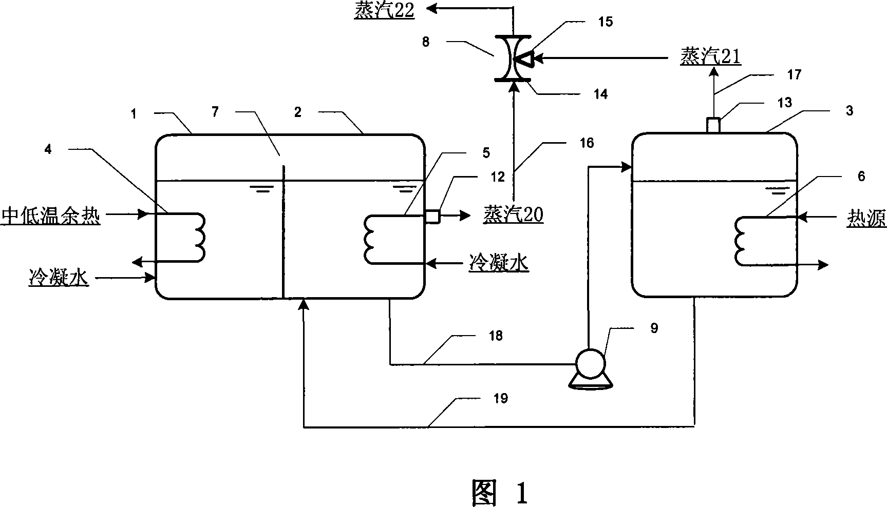
[0024] As shown in Figure 1, with the flue gas at about 500°C as the heat source of the generator 3, the absorption solution in the generator 3 is heated through the heat exchanger 6 placed in the generator 3 to evaporate and generate about 200°C, 0.2 MPa steam 21, while the concentration of the absorption solution in the generator 3 increases; the absorption solution of the generator 3 is introduced into the absorber 2. The absorption solution in the absorber 2 absorbs the steam from the evaporator 1 and generates absorption heat, heats the condensed water through the heat exchanger 5 placed in the absorber 2, makes it evaporate and generates steam 20 at about 150°C and 0.5 MPa, and at the same time The concentration of the absorption solution in the absorber 2 decreases. With the low-temperature flue gas at about 250°C as the heat source of the evaporator 1, the condensed water in the evaporator 1 is heated through the heat exchanger 4 placed in the evaporator 1 to evaporate...

Embodiment 2

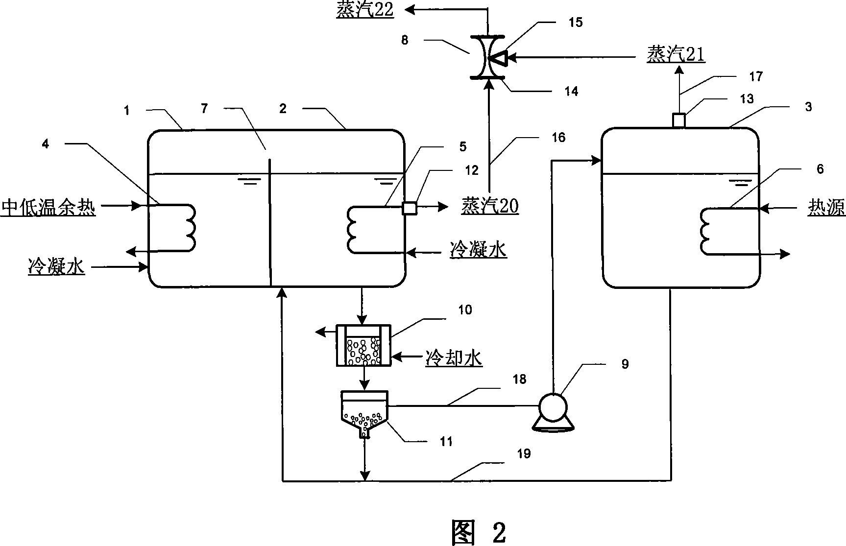
[0026]The first system of the present invention has the advantage of simple process, but has the disadvantage of low pressure of the produced steam. This is due to the mutual restriction of the working concentration of the absorber absorption solution and the working concentration of the generator absorption solution. In order to further increase the produced steam pressure, the second system of the present invention is shown in Fig. 2, and its process characteristic is that a cooling crystallizer 10 and a solid-liquid separator 11 are set between the absorber 2 and the generator 3. This embodiment is the same as the above-mentioned first embodiment, the low-temperature flue gas of about 250° C. is used as the heat source of the evaporator 1 , and the flue gas of about 500° C. is used as the heat source of the generator 3 . Steam at about 90°C is generated in the evaporator 1, and the steam enters the absorber 2 through the connecting channel 7; in the absorber 2, the absorpti...


PUM


Abstract

It is a system and method about excess heat transforming into steam at temperature, it belongs to the technology field of energy technology, heat energy engineering and material engineering which intercross with each other. The open-circuit circulatory system consists of evaporator, absorber and generator, cooling crystallizer and solid-liquid separator are set between absorber and generator. Lead the steam of generator to outside, make full use of it and condensate it, actually, put the condenser outside. Use medium-high temperature heat reservoir of 300-1300deg.C as generator, and use medium-low temperature excess heat of 90-300deg.C as heat reservoir of evaporator, at the same time, get steam from absorber and evaporator. The advantage lies in that, heat recovery efficiency is high, Every middle temperature excess heat or low loading of energy and one low temperature excess heat can produce 2 medium-low pressure steam; the procedure is simple, and the fabrication cost of the equipment is low.

Description

technical field [0001] The invention belongs to the intersecting technical fields of new energy technology, thermal energy engineering, chemical engineering and material engineering, and particularly relates to a system and method for converting medium and low temperature waste heat into steam. Background technique [0002] As my country's economic development has entered a new stage of pursuing circular economy, further energy saving and consumption reduction has become an important issue that high-energy-consuming industries such as steel, chemicals, and building materials must face. [0003] After years of hard work by the company, most of the high-grade waste heat and exhaust gas in the factory have been effectively utilized, so the remaining room for tapping potential is mainly low-grade energy with low grade, large quantity, and difficult reuse, that is, the temperature range In the middle and low temperature waste heat of 90-500 ℃. Typical medium and low temperature ...

Claims


Application Information

Patent Timeline
IPC IPC(8): F25B15/00F25B15/06
CPCY02B30/62Y02A30/27
Inventor 苏庆泉王立米万良
Owner UNIV OF SCI & TECH BEIJING
Why Eureka
Try Eureka