Clock recovery circuit used in non-contact IC card and radio frequency identification label

A radio frequency identification tag, clock recovery technology, applied in logic circuits, electrical components, automatic control of power, etc., can solve the problems of narrow field strength, variation, and difficulty in recovering clock signals.

Active Publication Date: 2007-09-19
SHANGHAI HUAHONG INTEGRATED CIRCUIT
View PDF0 Cites 4 Cited by
  • Summary
  • Abstract
  • Description
  • Claims
  • Application Information

AI Technical Summary

Problems solved by technology

This circuit structure adapts to a narrow range of field strength, especially for relatively small antenna signals, it is difficult to rec

Method used


Image

  • Clock recovery circuit used in non-contact IC card and radio frequency identification label

Examples


Embodiment Construction

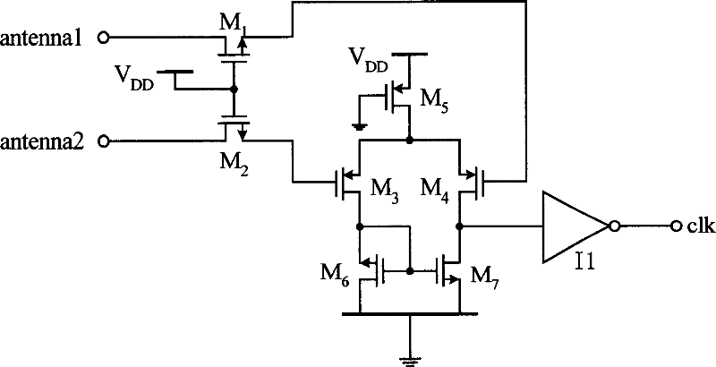
[0011] As shown in the figure, the clock recovery circuit for non-contact IC card and radio frequency identification tag chip of the present invention includes an antenna, two transmission gates, a comparator and an inverter.

[0012] In a specific embodiment of the present invention, the transmission gate is composed of NMOS transistors M1 and M2. The comparator is composed of PMOS transistors M3, M4, M5, NMOS transistors M6 and M7, wherein transistors M3 and M4 are used as input stages, transistor M5 provides current for transistors M3 and M4, and transistors M6 and M7 are used as loads of transistors M3 and M4 .

[0013] There are two antenna input terminals on the non-contact IC card and radio frequency identification tag products, and the two antenna signals are differential, and the clock signal can be obtained by using these two signals at the same time. The most common way for differential signals is to use a comparator to get the output. However, since the peak volt...


PUM


Abstract

The invention discloses a clock recovery circuit for non-contact type IC card and radio frequency identified tag chip, wherein one ends of two transfer gates are connected to the terminal end of the chip, the other ends of which are connected to the two input ends of a comparator, the signal outputted from the comparator is reshaped by a phase inverter and outputted from the output end as a clock signal. The invention has a stable duty ratio and can be adaptable to the field density with wider range.

Description

technical field [0001] The invention relates to a clock recovery circuit, in particular to a clock recovery circuit for non-contact IC cards and radio frequency identification tag chips. Background technique [0002] In non-contact IC card and radio frequency identification tag products, the clock signal comes from the signal on the antenna. When this type of product is working, it may be very close to or far from the card reader. When the working distance is short, the field strength on the chip (card or label) is relatively large, and the peak signal on the antenna is very large; when the working distance is long, the field strength on the chip is relatively small, and the signal on the antenna The peak value is very small; if the field strength is relatively small and the chip is just in the load modulation state, the signal peak value on the antenna is even smaller. The clock of the chip needs to be recovered from the antenna signal, which brings difficulties to the cl...

Claims


Application Information

Patent Timeline
IPC IPC(8): G06K7/00H03L7/00H03K19/00
Inventor 任建军刘颖
Owner SHANGHAI HUAHONG INTEGRATED CIRCUIT
Why Eureka
Try Eureka