Optical fiber brag sensing network having survivable guarantee
An optical fiber sensing and network technology, applied in the direction of optical fiber transmission, ring network, transmission system, etc., to achieve the effect of reducing power loss and loss
- Summary
- Abstract
- Description
- Claims
- Application Information
AI Technical Summary
Problems solved by technology
Method used
Image

Examples
Embodiment Construction
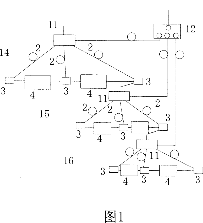
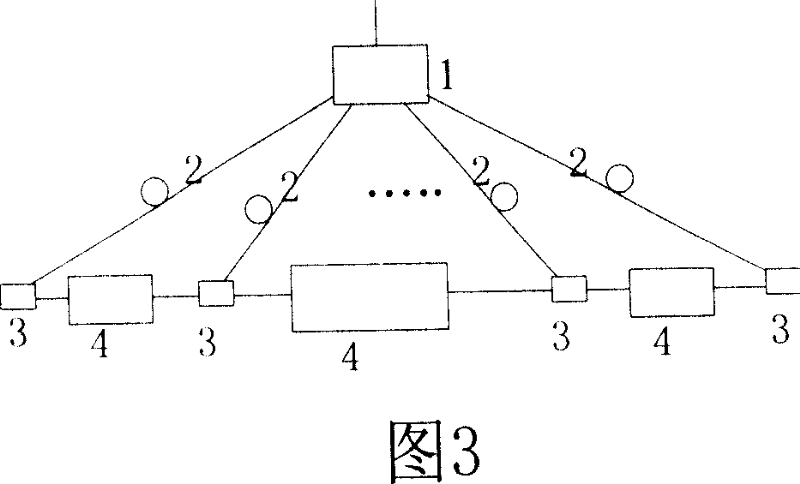
[0018] With reference to Fig. 1, a kind of optical fiber sensor network comprises at least first level subnetwork 14 and second level subnetwork 15, is characterized in that first level subnetwork 14 and / or second level subnetwork 15 adopts subnet module, Referring to Figure 3, the subnet module includes a master node 1 and at least two slave nodes 3, the master node 1 is connected to the slave nodes 3 through the transmission branch 2, and a sensing branch is connected between adjacent slave nodes 3 4. The output terminal of the slave node in the first-level subnetwork 14 is connected to the input terminal of the master node in the second-level subnetwork 15, and an optical switch 12 is connected to the optical sensor signal feedback terminal of the master node in each level of subnetwork And the optical sensing signal feedback terminals of the master nodes in the subnets at all levels are respectively connected to the input terminals of the optical switch 12 .
[0019] The a...
PUM
 Abstract
Description
Claims
Application Information
 - Generate Ideas
- Intellectual Property
- Life Sciences
- Materials
- Tech Scout
- Unparalleled Data Quality
- Higher Quality Content
- 60% Fewer Hallucinations
Browse by: Latest US Patents, China's latest patents, Technical Efficacy Thesaurus, Application Domain, Technology Topic, Popular Technical Reports.
© 2025 PatSnap. All rights reserved.Legal|Privacy policy|Modern Slavery Act Transparency Statement|Sitemap|About US| Contact US: help@patsnap.com