Electrical charging coagulation method for dust in flue gas transfering pipeline

A dust charging and coagulation method technology, applied in chemical instruments and methods, electrode structure, power supply technology, etc., can solve the problems of low dust efficiency, high energy consumption, and bulky volume

Inactive Publication Date: 2007-10-03
DALIAN MARITIME UNIVERSITY
View PDF0 Cites 19 Cited by
  • Summary
  • Abstract
  • Description
  • Claims
  • Application Information

AI Technical Summary

Problems solved by technology

[0005] The purpose of the present invention is to solve the problems of low efficiency, bulky and high energy consumption of the current elec

Method used


Image

  • Electrical charging coagulation method for dust in flue gas transfering pipeline
  • Electrical charging coagulation method for dust in flue gas transfering pipeline

Examples


Embodiment Construction

[0031] Specific embodiments of the present invention will be described in detail below in conjunction with the technical solution and the drawings.

[0032] step 1.

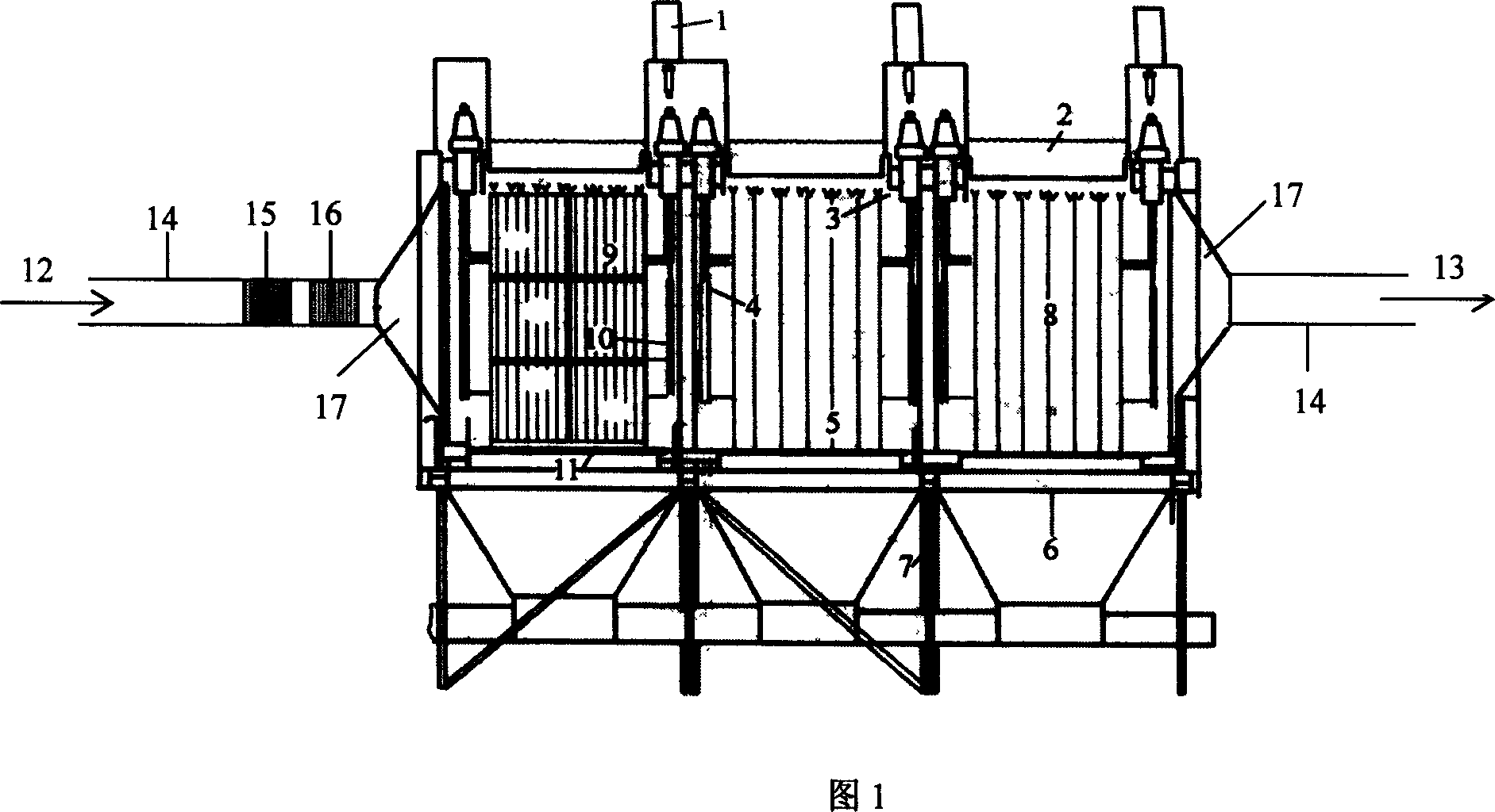
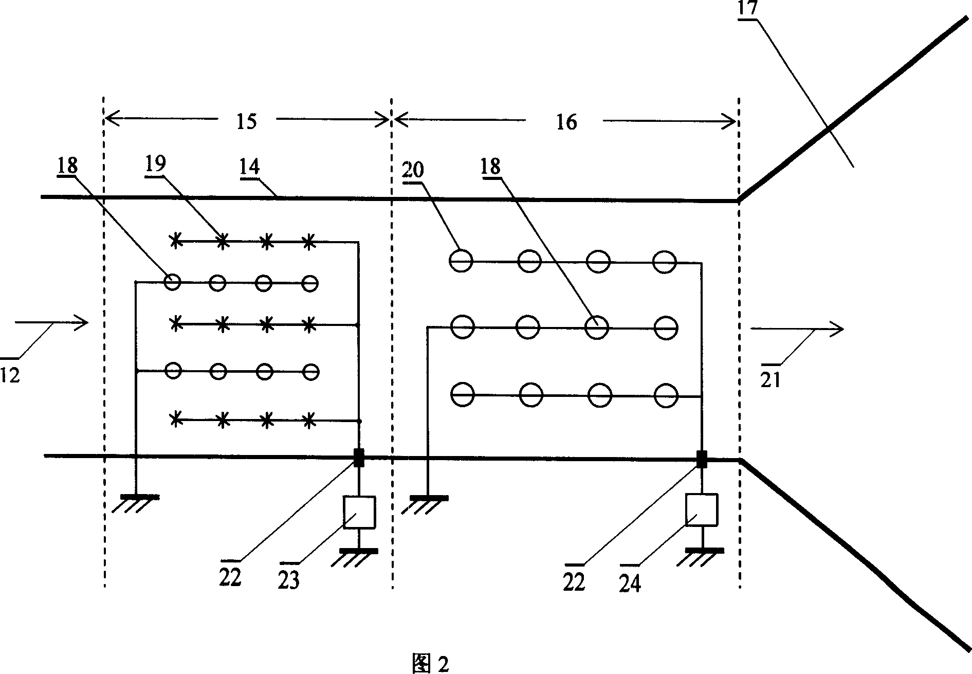
[0033] In the flue gas conveying pipe 14 of the inlet flue gas 12 in Fig. 1, a dust charging device 15 and a dust condensing device 16 are provided. The dust condensing device should be placed near the front end of the inlet air hopper 17 of the electrostatic precipitator. Place it at the front of the dust flocculating device. According to requirements, 1 to 4 sets of dust charging and condensing treatment devices can be installed in the flue gas conveying pipeline at the entrance of the electrostatic precipitator.

[0034] Step 2.

[0035] In Fig. 2 the discharge electrode 19 of the pre-charging device 15 is composed of metal circular, star, zigzag or fishbone electrodes; the ground electrode 18 is a narrow metal plate, cylindrical, elliptical or It is composed of round wire and other electrodes. The discharge elect...


PUM


Abstract

A method for electrically charging and coagulating powder dust in the fume delivering pipeline features that the charging and coagulating reaction of powder dust is performed at the entrance of an electric duster to make the dust particles be electrically saturated and to increase their diameter by 4-400 times, so increasing the dusting efficiency.

Description

Technical field [0001] The invention belongs to the technical fields of gas ionization discharge, plasma physics, gas dynamics, environmental engineering and the like, and relates to a method for charging and condensing dust in a flue gas pipeline. Background technique [0002] China has entered the 21st century with a relatively high economic growth rate and will consume more energy. Coupled with the rapid development of my country's building materials, steel, chemical, and non-ferrous metals industries, soot pollutants will increase substantially. It has caused harm to environmental and ecological safety and residents' health. At the same time, the application of electric precipitator (ESP) in thermal power plants, steel plants, and cement plants will achieve rapid development. At present, the number of electrostatic precipitators accounts for 75% of the total domestic market, and China has become the world's largest producer and application of electrostatic precipitators. In 2...

Claims


Application Information

Patent Timeline
IPC IPC(8): B03C3/01B03C3/68B03C3/40
Inventor 白敏菂张芝涛白敏冬杨波薛晓红白希尧
Owner DALIAN MARITIME UNIVERSITY
Why Eureka
Try Eureka