Blowby gas ventilator and crankcase emission control system of internal combustion engine

A technology of blow-by gas and control system, which is applied in the field of blow-by gas ventilator and crankcase emission control system, which can solve the problems of decreased productivity, unsmooth flow of blow-by gas and complicated passage of blow-by gas and other issues, to reduce weight, maintain injection efficiency, and reduce costs

Inactive Publication Date: 2007-10-03
HONDA MOTOR CO LTD
View PDF1 Cites 4 Cited by
  • Summary
  • Abstract
  • Description
  • Claims
  • Application Information

AI Technical Summary

Problems solved by technology

[0006] However, in the technique described in JP-A No. 4-246217, a vapor-liquid separation device is integrally attached to the exhaust pipe, and a U-shaped pipe is connected between the inlet and outlet of the vapor-liquid sep...

Method used


Image

  • Blowby gas ventilator and crankcase emission control system of internal combustion engine
  • Blowby gas ventilator and crankcase emission control system of internal combustion engine
  • Blowby gas ventilator and crankcase emission control system of internal combustion engine

Examples


Embodiment Construction

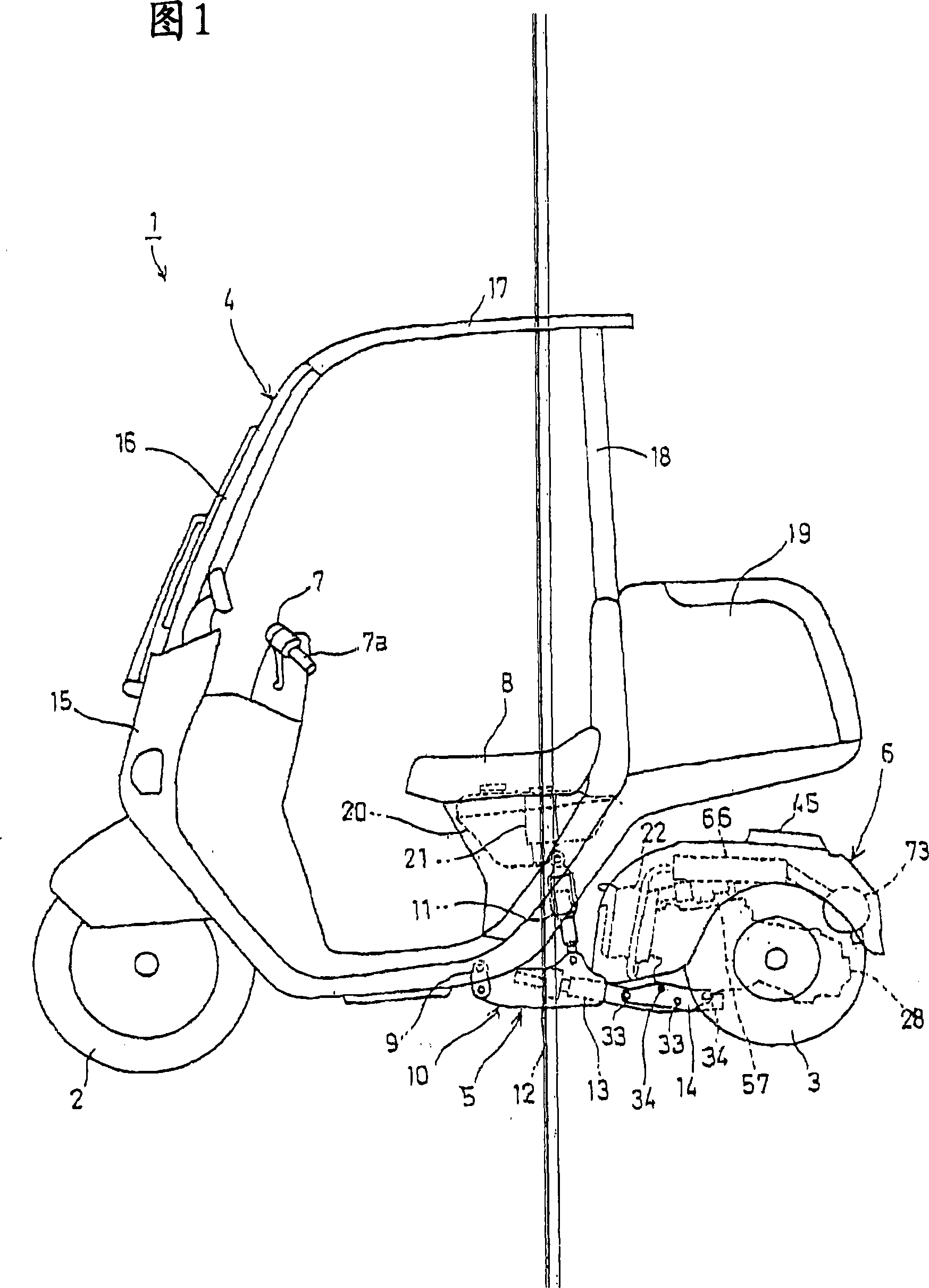
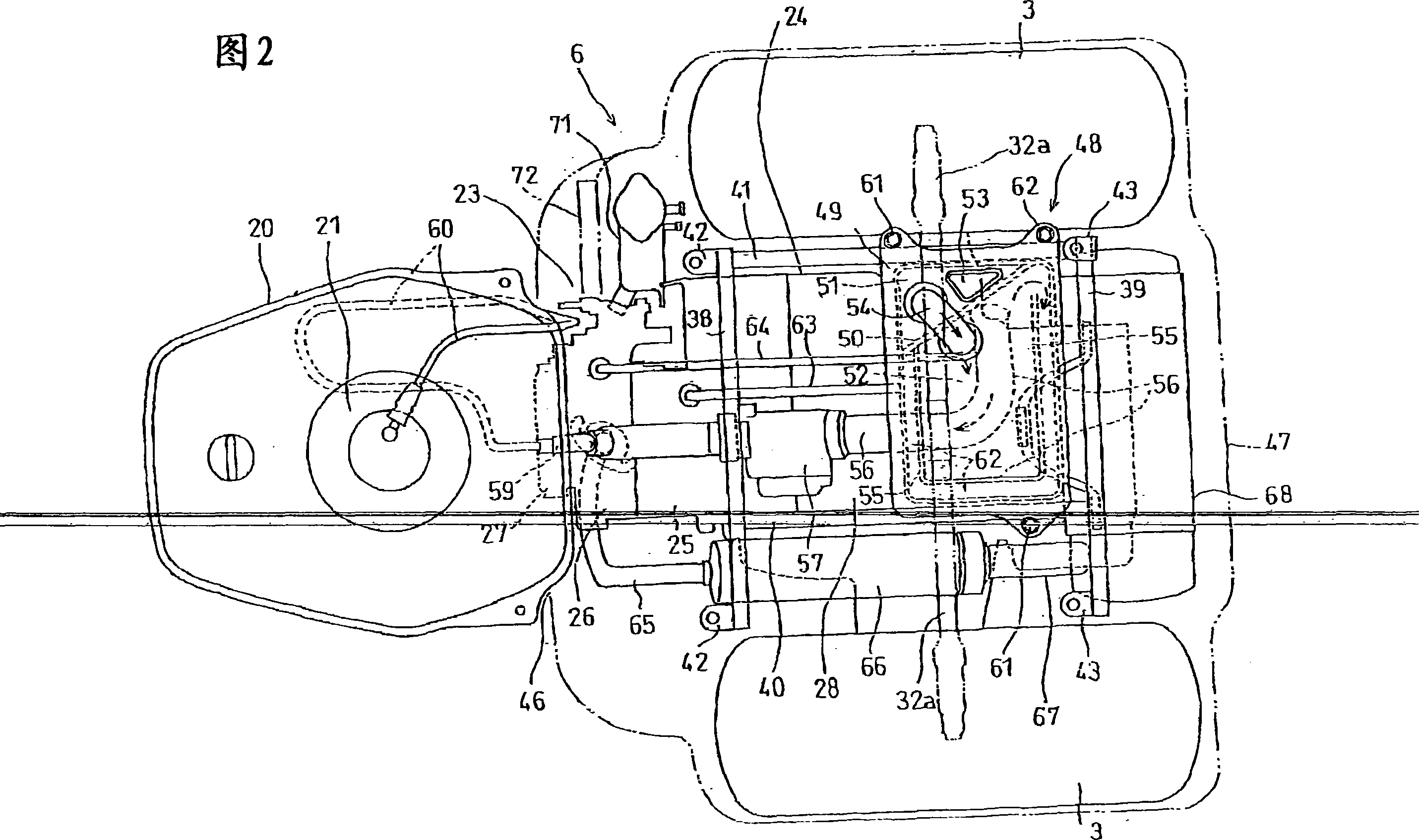
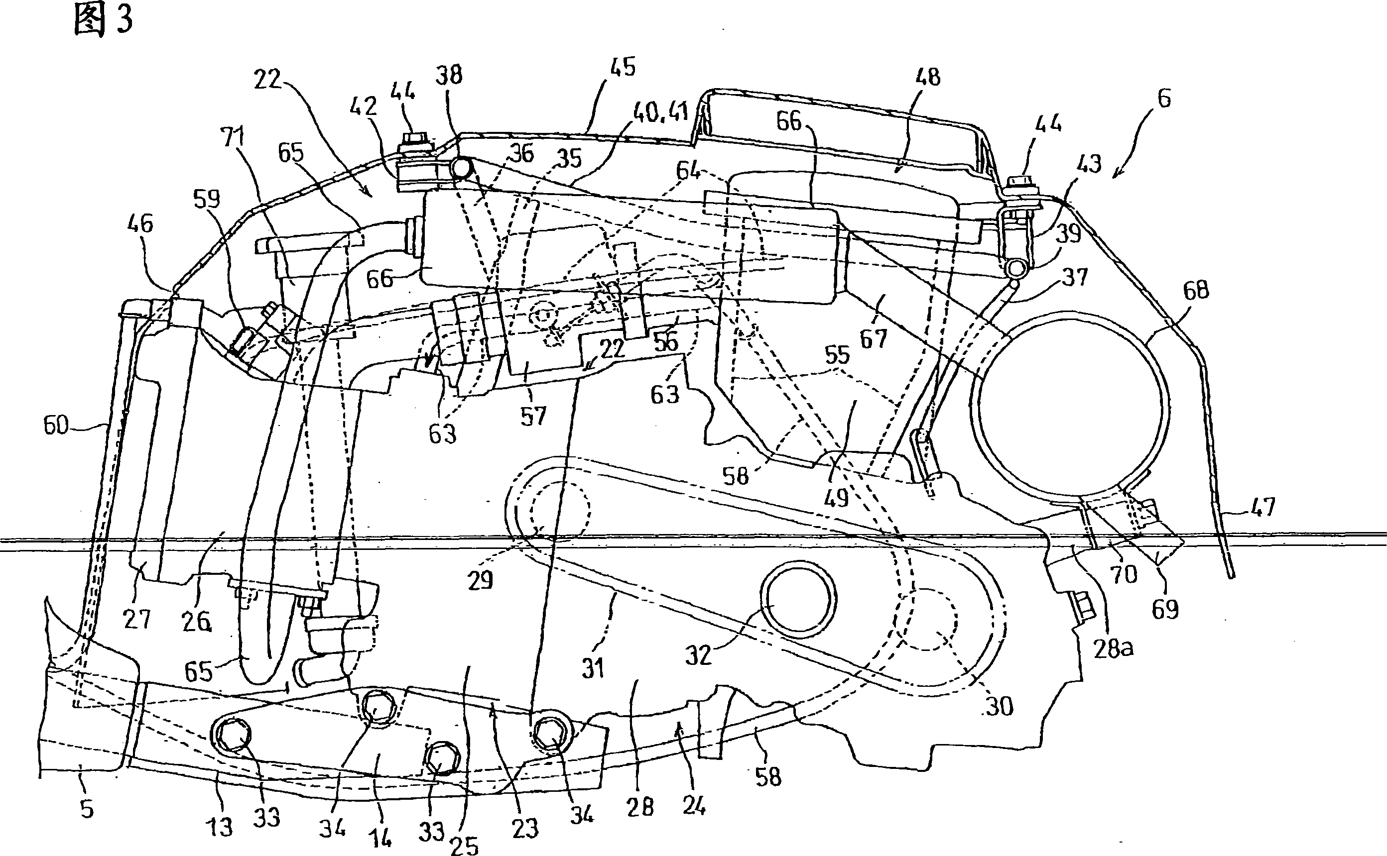
[0037] Embodiments of the invention as claimed in claims 1 to 3 will be described below with reference to FIGS. 1 to 3 .

[0038] A three-wheeled motor vehicle as shown in FIG. 1 includes a front wheel 2 and a pair of right and left rear wheels 3 . The front wheels 2 are rotatably mounted to the lower portion of an unillustrated steering shaft pivotally supported in front of the front body 4 in a substantially upright posture. The pair of right and left rear wheels 3 are arranged on both sides of a rear body 6 , which is located behind the front body 4 and connected thereto via a swing mechanism 5 .

[0039] The handlebar 7 that is used to manipulate the front wheel 2 is arranged on the top end of the steering shaft not shown in the figure, and the driver who is sitting on the vehicle seat 8 behind the front body 4 manipulates the handlebar 7, In order to make the front wheel 2 turn right or left.

[0040] Furthermore, the swing mechanism 5 includes: a connection box 10, whi...


PUM


Abstract

In an internal combustion engine, a part of fresh air extracted from an induction system is heated and introduced into a crank chamber to increase a temperatu re of an atmosphere in the crank chamber to promote atomization of a blowby gas to prevent water in the blowby gas from mixing into lubricating oil as much as possible to suppress deterioration of lubricating oil. A part of a blowby gas recirculating apparatus is defined by an outer space of a double-walled structure of a double-walled exhaust ga s purification catalyst or exhaust pipe provided between an internal combustion engine and an exhaust muffler. Thus, a blowby gas can be effectively heated with a high-temperatur e exhaust gas, the structure can be simplified, and a cost can be lowered.

Description

technical field [0001] The present invention relates to a blow-by fan for an internal combustion engine for heating fresh air from an intake system and introducing the air into the crank chamber in order to direct the blow-by gas in the crank chamber to the intake air recirculation within the system. [0002] The present invention relates to a crankcase emission control system for an internal combustion engine, in which a part of a blow-by gas recirculation device for recirculating blow-by gas generated in the internal combustion engine into the intake system is composed of a double wall The exhaust gas purification catalyst or the external sealing space of the exhaust pipe is limited. Background technique [0003] In an internal combustion engine, exhaust gas combusted in the combustion chamber partially leaks into the crank chamber as blow-by gas from a gap (albeit a small amount) between the cylinder wall and the piston outer peripheral wall. If moisture contained in th...

Claims


Application Information

Patent Timeline
IPC IPC(8): F01M13/00F01M13/04
CPCY02T10/16Y02T10/12
Inventor 菊池一纪五十岚和则
Owner HONDA MOTOR CO LTD
Why Eureka
Try Eureka